Standards prescribe integrating sphere size based on luminaire size, but MIKOŁAJ PRZYBYŁA explains that, for many product development and test purposes, a smaller sphere can deliver acceptable measurement accuracy.
Integrating spheres are fast and convenient tools for measuring the radiant or luminous flux of light sources. Such spheres are routinely used to characterize light sources such as packaged LED components and finished luminaires of all sizes. Clearly product-development and test-and-measurement teams want to document accurate results from sphere tests. But measurement practices prescribed in some standards can result in high cost associated with the need for very large spheres. Let's consider a set of laboratory tests that sought to determine how much accuracy was impacted when a smaller-than-prescribed sphere was used for routine tests - not undertaken for the purpose of reporting accredited laboratory results.
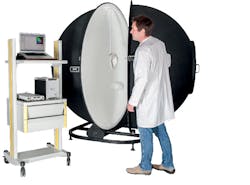
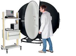
Fig. 1. A 2m sphere takes significant space and is mandated to be much larger than the luminaire under test by CIE standards.
Maximizing measurement system accuracy requires consideration of several variables during the selection and use of system hardware and software, particularly if one is strictly compliant to CIE standards. Since this compliance imposes significant size and cost demands, many companies would like to understand how compromises affect measurement accuracy. The compromises can minimize routing costs related to testing so long as accuracy can be shown to meet the requirements of the task at hand.
Selection of sphere diameter
Measurements compliant to the CIE S 025/2015 standard for LED product measurements must follow specific size requirements. There are two common sphere measurement geometries - 2π and 4π. The 4π configuration is most commonly used and requires that the DUT (device under test) be installed at the sphere's center. In tests where a light source does not radiate backwards, you can more conveniently measure total flux with the DUT mounted externally to the sphere with radiation into a port in the side of the sphere - referred to as a 2π geometry.
In a 4π measurement geometry, the DUT must have an area ≤2% of the sphere's inside diameter. This corresponds to DUT area that is 1/10 of the sphere diameter. For 2π measurements made externally, the port diameter must be ≤1/3 of the sphere diameter.
The CIE S025 standard is a global document aimed at harmonization of LED measurements in all countries around the world. The provisions of this regulation are available now in the European and American IESNA light measurement standards.
The net result is that only small-diameter lamps can be measured in most practically-sized integrating spheres. Fig. 1 depicts a 2m GL Opti Sphere 2000 that dwarfs the luminaire under test. Larger sources and luminaires must be measured in very large integrating spheres or by using a goniometer. Large integrating spheres, e.g. over 3m in diameter, are expensive and demand a large laboratory space. Equally expensive goniometers require constant ambient conditions and large distances from the light measurement instrument. Both solutions are beyond the reach of many companies and institutions for everyday engineering and test tasks.
Breaking the rules
So what happens when the "golden rules" of integrating sphere measurement are broken when measuring very large DUTs? In practice, companies testing to an internal standard, as opposed to those seeking accredited laboratory status, have adopted measurement practices allowing luminaires up to 30% of sphere diameter. The expected measurement uncertainty under laboratory conditions for this practice is 3-4%.
With relatively smaller spheres and large DUTs, the error increases as the DUT restricts sphere reflections, translating into lower measurement accuracy. Still, what compromises can be considered while still enabling engineers to derive meaningful results for internal testing? In this article, we will detail tests that confirm a surprisingly small increase in uncertainty compared to strict adherence to the CIE standard.
Test configuration and methods
We first devised a measurement stand and set of DUTs that would simulate different luminaire sizes. Essentially, each DUT relied on the same LED mounted on housings of different sizes and shapes that simulated different scenarios of DUT test interference.
Our tests were conducted with a GL Opti Sphere 1100 spherical spectroradiometer, consisting of a 1100-mm diameter integrating sphere and GL Spectis 1.0 spectroradiometer with a spectral range of 340-780 nm. The measurement system was calibrated, however, for the requirements of this set of experimental measurements that used a reference or base test of measuring just the LED atop the rod or measuring stand. The base case featured the smallest of the DUTs. The results of other DUT configurations were compared to the base case. Fig. 2 shows the different DUT configurations.
Our laboratory team maintained strict measurement conditions throughout the testing of each DUT configuration:
• Programmable stabilized TDK lambda power supply
• Constant LED integration time and LED switch-on time
• LED cooling between measurements for 3 minutes or more
The tests on each DUT configuration were repeated several times. The DUT was a phosphor-converted white LED dissipating 5.6W at a drive current of 0.6A.
Evaluating the results
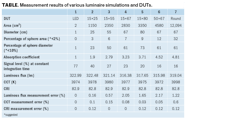
The derived results were better than expected. Even when recommendations given in the standard were exceeded by several times, the errors were in the range of only 2%.
The impact of the housing size and structure was surprising. Our 15×25-, 15×55-, 15×67-, 15×80-, and 50×67-cm DUTs were made of black foam while a round DUT was made of a light-colored cardboard that filled most of the sphere volume. The latter generated a smaller flux measurement error than the smaller black foam DUTs. The measurement results are presented in the table.
Conclusions
Accredited-lab testing must of course comply with applicable standards. But in internal testing, companies will find that luminaire size changes correlate to very small differences in luminous flux and colorimetric value measurements.
As DUT size got larger, the reading of luminous flux decreased and the necessary self-absorption compensation was significant. However, after recalculation, the measurement results were very repetitive. This means that a well-designed measurement system with a reflective coating layer index higher than 97% gives over a dozen reflections in the sphere, even with relatively large DUTs.
It must be noted that the self-absorption coefficient for the sphere-spectroradiometer system should be defined for each wavelength so its total defines the flux absorbed by the measured object. Depending on the object size and color, the coefficient can be different in the entire measurement range, necessitating the use of an accurate spectroradiometer or spectrometer.
More general conclusions on the measurement principle defined in the standard require additional tests and comparisons of different measurement systems. However, as the results prove when the right system and practices are used, repetitive and credible measurements can be obtained for light sources significantly larger than stipulated in the standard.
References
1. CIE S 025/E:2015 Test method for LED Lamps, LED Luminaires and LED Modules, Vienna 2015.
2. Y. Ohno, "Integrating Sphere Measurements for CIE S025," CIE Tutorial and Expert Symposium on CIE S025, Brauschweig, Nov. 24-26, 2015.
3. T. Bergen, "General Introduction to CIE S025," CIE Tutorial and Expert Symposium on CIE S025, Brauschweig, Nov. 24-26, 2015.
4. W. Dybczyński, "Optical radiation measurement," Białystok 1996.
5. PN-91 E-04040/01 Measurement and determination of light output , 1991.
6. Y. Ohno, "Luminous Flux and Spectral Radiant Flux Measurements," NIST Photometry Short Course, 2011.
7. M. Przybyła, LED lighting, No. 3/2016, "Practical tips for LED measurements according to CIE S 025 / E: 2015."
MIKOŁAJ PRZBYŁA is director at GL Optic Lichtmesstechnik GmbH.


