A potentially more-cost-effective approach uses metal-coated surfaces to reflect the light, which can be produced by depositing a thin — about 0.2‒0.5-µm aluminum (Al) layer — on a plastic mold6‒9. However, for many applications where high optical power densities above 1W/cm2 are required, such a reflector heats up and will exhibit damage due to surface modification, cracks, and even delamination.
In the following study, we demonstrate that by applying a metallic intermediate layer such as a combination of copper (Cu) and nickel (Ni) with a thickness greater than 30 µm, it is possible to dramatically reduce the maximum temperature of the reflector — in this experiment, from 117°C to 51°C — and obtain long-term stable operation of the reflector under high-power irradiation from UV LEDs.
Materials experiment
OSA Opto Light recently developed a scalable UV-LED light source comprising LED plates and parabolic reflector arrays that are designed to be placed side by side to create a line up to 120 cm long. The parabolic reflectors cause the light to be emitted at an angle of about 20°, and under each parabolic reflector one to four LED chips can be placed. The middle of Fig. 1 shows the shortest available module and the two approaches we have tested to produce the array of Al parabolic reflectors. On the left side, the reflector array is produced out of a full-Al material by computerized numerical control (CNC) milling followed by a surface polishing step. The polishing step is required due to the rough Al surface after milling. On the right side, the reflector array is produced by coating an Al layer on a plastic reflector mold. The plastic mold injection was performed at Khatod with polycarbonate (PC) and the Al coating was about 0.2 µm thick. This approach does not require any polishing, thus keeping production costs low. The table summarizes the advantages and disadvantages of each production technique.
The metallic reflectors produced in this study were investigated regarding coating thickness with a scanning electron microscope and a focal light microscope. Some reflectors were tested in a small LED unit with two reflector arrays similar to the one shown in Fig. 1. An infrared (IR) camera and thermometers were used to study the temperature during operation of the devices, and a gallium phosphide (GaP) detector was used to examine optical output.
UV reflector simulation
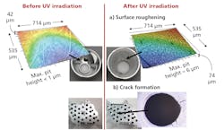
Fig. 2 represents examples of the effect that high-power UV irradiation has on the thin Al film coating the plastic reflectors. The upper images (a) show how the Al surface deformed under the influence of 1W (365-nm) irradiation for 5000 hours. Initially, the surface roughness had a maximum pit height of less than 1 µm, which increased after UV irradiation to about 6 µm. The lower images (b) show how the UV irradiation caused cracks at the bottom of the reflector array after a few hours of operation at an optical power of 1.5W per parabolic reflector (390 nm).
The appearance of surface roughness and cracks on the Al-coated plastic reflector seen in Fig. 2 is related to the high temperatures that develop at the Al layer. Since the plastic has a low thermal conductivity — e.g., 0.2W/mK for PC10 — the main heat transport path is through the Al layer. However, since this layer is only 0.2 µm thick, under high-power UV irradiation it cannot conduct all the heat absorbed; thus, under such UV irradiation, temperatures can exceed 100°C. Attempts to coat the plastic mold with a thick Al layer mostly result in rough layers that have diminished optical quality or even delaminate7,11. The approach we took in this work was to deposit a thick intermediate layer such as Cu and Ni combined or chrome (Cr) alone by electroplating on the plastic mold and afterwards lay the Al coating on top.
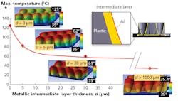
In order to estimate how thick the metallic intermediate layer should be to efficiently reduce the maximum temperature of the reflector, we performed a finite element simulation with the program ANSYS 19.1. Fig. 3 shows the results obtained for four different thicknesses of metallic intermediate layer: d=0 (no layer), d=5 µm, d=30 µm, and d>1000 µm (full metal reflector). An illustration of the intermediate layer (marked in yellow) can be seen in the upper right corner of the figure. The simulation was performed with an optical power of 1.5W UV light for each parabolic reflector and intermediate-layer thermal conductivity of 200W/mK. The cut reflector-array images illustrate the temperature distribution obtained by these four simulations and the graph shows the maximum temperature reached for each of the simulations. Fig. 3 shows that a 5-µm-thick metal layer can reduce the reflector temperature from 125°C to 82°C (by 35%). Further increasing the intermediate layer to 30 µm reduces the reflector temperature 125°C to 60°C (by 52%), which is only 25° above the full metal reflector. For intermediate thicknesses above 30 µm, the maximum temperature does not drop significantly and saturation is reached. Fig. 3 demonstrates that any intermediate layer greater than 30 µm would be sufficiently thick to obtain optimal heat conductivity properties nearly equivalent to a full metal reflector.
Reflector results
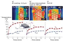
Based on the theoretical simulation, we have prepared arrays of parabolic reflectors with a roughly 100-µm-thick Cu/Ni intermediate layer and compared them to Al-coated reflectors with no intermediate layer as well as to full-Al reflectors. Fig. 4 shows the results of the temperature measurements on these three types of reflectors irradiated with 1.5W under each parabolic reflector with a wavelength of 390 nm. The upper images were taken by the IR camera after 12 minutes of module operation and the lower graphs display the temperature over time after turning on the LED module. Tout marked with blue is the temperature result of the sensor cable that was attached to the side wall of the parabolic array, and Tin marked with red is the temperature result of the sensor cable inside the parabolic array. The temperature values of Tin were found to be somewhat above the maximum temperature measured with the IR camera due to the fact that the sensor cable was exposed to the UV irradiation and had an additional heat contribution directly from the light. Nevertheless, the quantitative difference between the reflector with and without the intermediate layer can be clearly seen also for Tin. The IR images corroborate that the maximum stabilized temperature of the reflector without an intermediate layer is 117°C, whereas with the intermediate layer it is as low as 51°C, which is only 5°C above the full-Al reflector. Intermediate layers composed of Cr also showed a significant reduction in temperature, but in our experiment the best results were obtained with a combination of Cu and Ni.
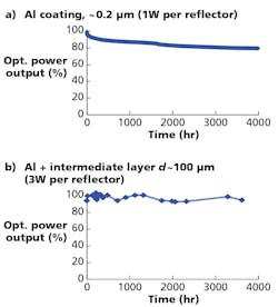
A continuous irradiation test over 4000 hours was performed to test the effect of the Cu/Ni intermediate layer on the long-term stability of the reflector array. Fig. 5a shows the optical power output obtained from a parabolic reflector without an intermediate layer irradiated with 1W UV per reflector (390 nm), whereas Fig. 5b shows the optical power output obtained from a reflector with a 100-µm-thick Cu/Ni intermediate layer irradiated with about 3W UV per reflector (390 nm). Although the reflector with the intermediate layer is irradiated with 3× more optical power, it does not exhibit any degradation within the experimental error of ±3%. On the contrary, for the parabolic reflector without an intermediate layer, which is irradiated with 3× less UV power, a degradation of about 20% is observed.
Conclusion
In the framework of this study, our team has demonstrated that adding a metallic intermediate layer to an Al-coated plastic reflector is a promising approach to achieve a high-power-compatible UV reflector with excellent heat conductivity properties. Using a finite-element thermal simulation, we were able to confirm that the intermediate layer thickness should be greater than 30 µm to achieve optimal performance. The reduction in reflector temperature is shown to significantly improve the lifetime of this optical element with no degradation observed under harsh UV irradiation conditions for 4000 hours. This technological solution is expected to smooth the way for next-generation, high-power UV light sources.
ACKNOWLEDGMENTS
The authors wish to acknowledge the financial support for this work provided by the German Federal Ministry of Education and Research within the program “Twenty20 ‒ Partnership for Innovation.”
Special thanks go to Rolf Baldauf for executing the thermal simulation with ANSYS 19.1; Holger Rhein from PVcomB for performing focal microscopy measurements on some reflectors; and the team at OSA Opto Light for supporting the research and development activities.
REFERENCES
1. C. Mendes-Felipe et al., “State-of-the-Art and Future Challenges of UV curable Polymer-Based Smart Materials for Printing Technologies,” orig. publ. Adv. Mater. Technol., 4, 1800618 (2019).
2. M. Kneissel and J. Rass, III nitride Ultraviolet Emitters: Technology and Applications, Springer, p. 310 (2018).
3. S.E. Beck et al., “Action spectra for validation of pathogen disinfection in medium-pressure ultraviolet (UV) systems”; orig. publ. Water Res., 70 (2015).
4. Advanced UV for Life Consortium, “UV LEDs for New Applications: Status and Perspectives 2018.”
5. C. Todaro, Khatod presentation, “Development and Production of Secondary Optics in LSR.”
6. S.M. Muralidhar et al., “Studies on Nanostructure Aluminium Thin Film Coatings Deposited using DC magnetron Sputtering Process,” orig. publ. IOP Conference Series: Mater. Sci. and Eng., 149, 012071 (2016).
7. L. Robert and S.K. Obwoya, “The Effect of Thickness of Aluminium Films on Optical Reflectance,” J. Ceramics, Article ID 213635 (2015).
8. H. Hukkannen, International Patent, “A Light Guide System,” WO2014/188066A1.
9. J.R. Householder et al., US Patent, “Reflective Variable Spot Size Lighting System,” US 2012/0140478 A1.
10. X. Zhang et al., “Measurements of the Thermal Conductivity and Thermal Diffusivity of Polymer Melts with the Short-Hot-Wire Method,” orig. publ. Intl. J. Thermophys., 23, 1077–1090 (2002).
11. P. Quintana, A.I. Oliva, O. Ceh, and J.E. Corona, “Thickness effects on aluminum thin films,” orig. publ. Superficies y vacío, 9, 280‒282 (1999).
Get to know our experts
M. WEIZMAN, A. RUH, S. CINQUE, P. ROTSCH, and W. ARNOLD are with OSA Opto Light GmbH; S. NIELAND is with CiS Research Institute for Microsensors; and C. TODARO is with Khatod.

![FIG. 1. Shown is an ultraviolet (UV) LED light source designed by OSA Opto Light with parabolic reflector arrays produced out of either full aluminum [Al; (a)] or a thin Al layer on a plastic mold (b). Image credits: All illustrations courtesy of OSA Opto Light. FIG. 1. Shown is an ultraviolet (UV) LED light source designed by OSA Opto Light with parabolic reflector arrays produced out of either full aluminum [Al; (a)] or a thin Al layer on a plastic mold (b). Image credits: All illustrations courtesy of OSA Opto Light.](https://img.ledsmagazine.com/files/base/ebm/leds/image/2019/10/1910LED_DevF1.d.5dadf284b949f.png?auto=format,compress&fit=max&q=45&h=190&height=190&w=250&width=250)


