Although gains in device efficiency have enabled LEDs to supplant fluorescent, incandescent, and metal halide lighting technologies, manufacturers continue to design luminaires around these traditional illumination sources. This article series will limit its discussion to the most prolific luminaire in commercial lighting applications (office, education, and healthcare): the semi-indirect linear luminaire, which was populated by linear fluorescent lamps in the previous paradigm.
In addition to designing LED semi-indirect luminaires around linear fluorescent lamps, many established manufacturers adhere to traditional manufacturing and supply chain models, which limit features that can provoke more circular design. Additive manufacturing — or 3D printing — can facilitate new feature systems that use less material, promote design for disassembly, and enable recycling in a way that is currently not realized in commercial lighting.
The L-Prize Concept Phase-winning “Sparkle” design was undertaken as a thought experiment: to develop a product encompassing many feature benefits of additive manufacturing which currently are not represented via traditional manufacturing techniques, while addressing systemic issues in commercial lighting applications.
By designing around the strengths of solid-state lighting technology instead of the previous technology, we can realize breakthroughs in spacing criteria and application efficiency, thereby reducing lighting power density. This allows us to employ fewer luminaires, equating to less material used and wasted.
In Part I of this two-part series, we will review the performance differences between fluorescent and LED luminaires in the common linear luminaire form factor, and examine how the Sparkle concept was initiated to address LED luminaire functionality — with an eye to performance improvements in thermal and optical design. Part II will explore the intersection of component modularity, flexibility in customization, and design for disassembly, which contribute to the potential of the luminaire concept to disrupt the conventional lighting manufacturing and distribution model.
Fluorescent paradigm influence on lighting product design
In the past paradigm of semi-indirect linear fluorescent luminaires, there existed a strict dichotomy: lamps and “fixtures.” Lamps — dominated by Philips, GE, and Osram Sylvania — were a commodity product. A limited number of SKUs went to market through distribution. Fixtures (luminaire housings) had myriad SKUs and grades (utility, architectural, and specification). Fixtures tended to be high-commodity products sold predominantly through local agency networks. The two components — lamps and luminaires — met at the job site.
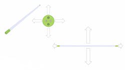
For decades, commercial fluorescent luminaires, which housed linear fluorescent lamps, delivered direct distribution only. Linear fluorescent lamps emit light omnidirectionally in the vertical axis (see Fig. 1, top). Reflectors were used in the top of direct-only luminaires to redistribute indirect light down toward the work plane, which often caused discomfort glare. Consequently, luminaire designers introduced louvers to shield direct viewing, which resulted in light losses, with some fixture efficiencies as low as 50%i. The advent of the semi-indirect linear luminaire resolved such issues. By in effect removing the top of the luminaires, the upward distribution that would normally be directed into reflectors was allowed to escape the luminaire unencumbered. Because of high reflectance common in commercial applications (80% for ceiling; 50% for walls; 20% for ground), this indirect light was reflected down to the work plane — supplementing the direct light component.
This proved efficient and effective. An average linear semi-indirect luminaire — using a linear fluorescent lamp with efficacy of 100 lumens/watt (LPW) — may have system efficacy of 70 LPWii. With common hang heights of 1.5 to 2 feet, these luminaires were closer to the work plane and produced less visual discomfort. This standard proved formidable enough to withstand the encroachment of LED technology for years after its initial deployment in commercial spaces. Thus the semi-indirect linear fluorescent luminaire became the template for the most common LED luminaire today.
How LEDs changed the game
With the introduction of solid-state luminaires in commercial lighting, the supply chain was disrupted. Lamps could no longer meet luminaires at the job site. The LED became critical to the inception of the product. With the exception of TLEDs, which have shown limited success in the market due to electrical configuration complexities with existing fluorescent ballasts, LEDs were embedded within the luminaires. The LED became pivotal to the initial mechanical design as well as the optical, electrical, and thermal engineering of the luminaire.
It is not unusual for manufacturers to design new lighting technologies in the image of the past technology given existing market acceptance. However, in commercial lighting, the attributes of LEDs do not make them appropriate replacements for linear fluorescent.
First, LEDs are not omnidirectional in the vertical axis. Their radiation pattern is limited to 170° to 180°. In order to match the radiation pattern for a linear fluorescent tube in a semi-indirect luminaire, two sets of LEDs are necessary: one illuminating up, the other down. LEDs are often the most expensive element of the bill of materials (BOM,) so cost increases. Moreover, given that LEDs are dynamic devices, doubling the number of LEDs increases the burden of balancing electrical loads among multiple strings of LEDs. Passive devices to mirror current among the strings become necessary, which also increases costs.
Then we must consider horizontal illumination. One of the critical limitations of linear fluorescent technology is the bilateral symmetry that results from the endcaps blocking emissions (see Fig. 1, bottom).
This asymmetric radiation pattern manifests both in the corresponding luminaires and the application. Irregular spacing became the standard to provide uniform illumination. The suspended linear fluorescent — 4 feet in length — begot 4×8 footiii spacing with the luminaires being installed conspicuously end-to-end.
This artifact of linear fluorescent technology is not inherent in LEDs, which are symmetric in the horizontal axis. Yet today LED semi-indirect luminaires are still installed in 4×8-foot, end-to-end configuration. This has resulted in a lost opportunity to reduce power density (W/ft2) in commercial buildings — a sector where lighting is responsible for 17% of the electricity usediv. While other applications have translated rapid increases in device efficiency into power density drops, the application benefits in commercial lighting have lagged.
Design methodology
Prior to discussing ways of improving the technology, it is helpful to see an application snapshot comparing the state-of-the-art linear semi-indirect LED and fluorescent lighting technologies.
IES files based on independent laboratory testing characterize the intensity distribution of both LED and fluorescent linear products. At Smash the Bulb, a lighting innovation incubator, we used these IES files in Visual Lighting Softwarev to model the lighting in the application. A survey of competitive semi-indirect LED luminaires was undertaken, and the best performer in ceiling and work-plane uniformity as well as power density was chosen. We used this company’s LED semi-indirect luminairevi as well as the application conditions (60×60×9 feet) its team used in their collateral to show best-use cases. Reflectivity in the room was set to (80/50/30). Illuminance readings were set to a grid of 2×2 feet on both the work surface and the ceiling. Light-loss factor for each luminaire was set to 0.9 with a ballast/driver factor of 1. Linear fluorescent performance based on independent lab testingvii in compliance with LM-79 protocol was also used for fair comparison. The results are included in Table 1.
The table data illustrate that, while power density has dropped over the last decade, other performance metrics such as spacing are worse than they were during the fluorescent paradigm. In this specific example pulled from the best-of-class collateral, the spacing between luminaires was 4×15 feet, while spacing for the fluorescent was 4×18 feet, which increased the number of fixtures by 25%. In addition, ceiling uniformity appears not to have improved substantially over the last decade in the application.
Based on this observation, we set out to design around the strengths of the LED technology in commercial applications with the goal to create near-perfect uniformity on the ceilingviii. The first step was to find the ideal distribution, then see if there were ways to achieve it with existing, readily available components.
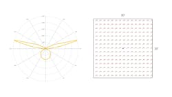
The ideal “rabbit ear distribution” was achieved through trial and error by creating multiple IES files and inputting them into the Visual light calculation software. A classroom-sized space (30×30×9 feet) was used with average reflectance (80/50/30). A single unit was suspended 1.5 feet below the ceiling and illuminance readings on a 2×2-foot grid on the ceiling plane were measured. The resulting distribution showed perfect 1:1 uniformity (see Fig. 2). We assigned a Lambertian distribution for the direct component of the lighting based on state-of-the-art downlight luminaires. While the nuances of the indirect distribution would be hard to achieve with off-the-shelf optics, we were able to approximate the core of the distribution. For the main beam shape, we were able to approximate the full width half maximum (FWHM) with an elliptical orthogonal optic with beam shape of 7°×50°. To approximate the peak candela, we matched the candela/lumen value of the opticix with an LED that was small enough (<2×2 mm) to allow for good flux coupling while being able to produce 300 lumens. The resulting 2400 peak candela was close to the ideal.
The resulting IES file was dropped into the previous room layout, described preceding Table 1, and the results can be seen in Table 2. Given the room size, the prototype Sparkle luminaire was spaced out on 15×15-foot centers in order to meet the minimum illumination standards of 20 fc. It was suspended, like the other linear luminaires, at 1.5 feet below the ceiling.
The “hero” distribution created noticeably better ceiling uniformity. Most important is the number of luminaires that were used. Sixteen units represents a 69% reduction in the number of luminaires needed, saving per-item and installation costs for the project. In addition, this scenario eliminated a great deal of materials for luminaires and packaging. Finally, the power density (W/ft²) was reduced by 60%. By designing around the strengths of the technology, we have been able to see breakthroughs in application efficiency, performance, and light quality.
Arrangement of the individual optics is critical to achieving horizontal symmetry and ceiling uniformity. With each LED/optic tilted to the ideal peak candle angle (104°), we could arrange eight of the optics in a circle and with a small overlap for each (50°) beam provide 360° coverage in the application. Instead of bilateral symmetry, poor uniformity on the ceiling, and end-to-end arrangement of the luminaires, this strategy allowed for wider and symmetric spacing. In defining the term “ubiquitous computing,” computer scientist Mark Weiser saidx that the most profound technologies disappear. An overarching request from designers to luminaire manufacturers over the years has been to develop products that blend in, don’t demand attention, and, in effect, disappear. Depopulation is the best strategy for achieving this goal.
Addressing mechanical properties and thermal components with additive manufacturing
The proposed Sparkle indirect engine, LED, and optical assembly require heat sinking. To house these uplight optics, we considered a single-piece heat sink and housing that could be realized through additive manufacturing.
As a tenet of circular design, material uniformity is a critical requirement in this thought experiment. With traditional manufacturing methods, a separate heat sink would be produced by cast metal; the product designer would need to reconcile any differences in appearance of the heat sink and the remainder of the product. They would also need to mechanically join the heat sink with the other elements of the product. Invariably that would require second operations on both the heat sink and the body of the luminaire to produce screw holes and enable attachments.
For ease of operations and disassembly, this is a non-optimal solution. We wanted Sparkle to deliver a completely toolless design for ease of assembly in the manufacturing cell as well as ease of disassembly in the field. Ultimately, we were able to create a housing and heat sink as a single monolithic component using the same material as the remainder of the luminaire.
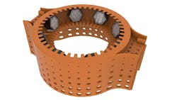
Working with the Lighting Research Center at Rensselaer Polytechnic Institute, an initial design for a 3D-printed heat sink was proposed and tested for its ability to mitigate heat buildup. Modifications were made to accommodate direct lighting elements as well as novel attachment mechanisms. The final uplight holder/heat sink component is shown in Fig. 3 with LED starboard and individual off-the-shelf optic in an array.
Additive manufacturing offers the ability to attempt high-risk design strategies that would not be cost effective or easily achieved through conventional manufacturing processes. For example, the uplight optic array is held in place via a friction fit with very slight tolerances (<0.1 mm). Prototyping this feature via 3D printing allowed the designer to bracket different cavity dimensions in order to find the best fit, and accurately anticipate the material behavior and flow for subsequent, high-volume additive manufacturing.
Sparkle louver
Louvers are commonly used in commercial lighting luminaires to mitigate discomfort glare. The initial Sparkle louver concept was born of a frustration with the light loss and poor fixture efficiencies exhibited by state-of-the-art louvered luminaires. Traditional fluorescent luminaires used sheet metal louvers, which were thin walled (<1 mm thick) and could have some level of specularity. The amount of light scattered back into the luminaire was minimized. However, the current trend in LED lighting is to use plastic louvers. With conventional manufacturing techniques and the molds being used, they are much thicker than their fluorescent predecessors. Wall thicknesses of 3 mm are not uncommon, thereby compromising fixture efficiencies.
The first requirement for the Sparkle louver was thin walls, and additive manufacturing enabled wall thickness <1 mm. We also realized that more holes could be added to the fins of the louver to allow more light to escape. Like the heat sink/uplight component, this component is only achievable through additive manufacturing. Molds would be unable to create all the features, and second operations couldn’t be performed on the part without damage.
Upon prototyping, we also noticed some unexpected effects. First, the thin walls of the louver mitigated direct viewing of the light source. However, being thin and plastic, they allowed a slight transmission of light. The glow from the louver fin itself was aesthetically pleasing and beneficial for subsequent illumination.
We also noticed that while viewing the louver from below, tiny pieces of the light source were able to be seen. This had a similar biophilic effect to that of dappled light seen while looking up into a dense canopy of trees in the forest. Previous research on the use of sparkle effects in applications came to mindxi. Sparkle — described as a narrow band between merely bright and glare — increased the perception of brightness in commercial lighting applications, allowing for reduced illumination levels and energy use. The Sparkle louver design may produce the same effect. For an added advantage, it can be easily removed for access to the LEDs and end-of-life disassembly.
Part I conclusions
Sparkle was undertaken as a thought experiment to present the unique advantages of additive manufacturing over traditional luminaire manufacturing techniques. Achieving performance breakthroughs in the application was an important requirement — specifically designing around the strengths of SSL instead of the previous illumination paradigm. Additive manufacturing facilitated this process by enabling fewer parts with no need for fasteners or adhesives. It also reduced the need for off-site, secondary modifications such as finishes. As previously noted, many of the features exhibited in Sparkle would not only be prohibitively expensive with traditional manufacturing techniques but would be impossible to produce in scale. For this reason, we consider the design a success.
Continue reading Part II of this feature.
Disclaimer: The design and concept of Sparkle discussed in this article are filed with the U.S. PTO and designated as Patent Pending.
REFERENCES AND FOOTNOTES
1. K.S. Hickcox and A. Smith, “Strategies for achieving circular economy goals in the lighting industry through design for disassembly-based methodologies,” Light-Symp-2022, IOP Conf. Series: Earth and Environmental Sci., 1099, 012004 (2022).
2. Y. Akashi, “Effect of sparkling luminous elements on the overall brightness impression,” Lighting Research and Technol., 32(1), 19–26 (2000).
iDOE Caliper Benchmark Report: Performance of T8 and T12 Fluorescent Lamps
iiAfter 20% fixture losses and 10% power supply losses
iiiSometimes 4×9 feet
ivCBECS 2012: Trends in Lighting in Commercial Buildings
vAcuity Brands Visual Lighting Software
viiITL62319, Independent Testing Laboratories, Inc.
viiiThis would address systemic application issues such as cave effect and hot spots with dark surrounds
ix8 candela/lumen
xM. Weiser, “Ubiquitous Computing”
xiY. Akashi, “Effect of sparkling luminous elements on the overall brightness impression,” Lighting Research and Technol., 32(1), 19–26 (2000).
DON PEIFER is a serial entrepreneur and lighting innovator based in Silicon Valley. With a master’s of architectural sciences in lighting from the Lighting Research Center at RPI, he has worked as a lighting designer and an executive in the lighting and controls sector for nearly two decades. Peifer was one of four winners of the DOE L-Prize Concept Phase. For more information on Sparkle, visit smashthebulb.com.
Follow our LinkedIn page for our latest news updates, contributed articles, and commentary, and our Facebook page for events announcements and more. You can also find us on the X platform.


