Tubular LED upgrades of fluorescent fixtures offer efficacy, energy consumption, and lifetime advantages over traditional fluorescent lighting, but it is essential to consider the options and tradeoffs when dimming and controls are involved, says ETHAN BIERY.
In existing buildings with older fluorescent lamps and fixtures, lighting retrofits can deliver significant energy savings, improve light quality, and reduce maintenance costs. An increasingly popular solution is to retrofit fluorescent fixtures with tubular light-emitting diode (TLED) retrofit options (also known as LED tubes).
Interested in articles & announcements on TLEDs & indoor lighting?
TLEDs can be easy to install, offer longer life, and reduce energy usage compared to fluorescent lighting as noted in a US Department of Energy (DOE) Caliper Snapshot report on linear LED lamps (see the news story). But there are tradeoffs, especially when a dimming control system is already in place, and high-performance dimming functionality is desired.
Before deciding on a TLED retrofit, consider the type of lighting performance necessary in the space. If the lighting needs to be fine-tuned and/or dimmed to low levels, TLEDs may not be able to deliver these benefits. Here we will consider three commonly-used TLED retrofit scenarios.
TLEDs retrofitted with existing fluorescent ballasts (UL Type A)
In the first scenario, the fluorescent lamps are replaced with specialized LED lamps that work with the existing ballasts. This type of TLED lamp has sophisticated internal electronics that simulate the electrical characteristics of a fluorescent lamp, essentially tricking the ballast into thinking a fluorescent lamp is still connected (Fig. 1).
fluorescent lamp by using internal electronics to "trick" the ballast into
behaving as though a fluorescent tube is still connected.
A significant benefit of this option is that installing TLEDs into existing fixtures requires minimal labor and no modification to existing wiring or sockets. It is a very simple solution but not without risks. The additional circuitry typically adds cost to the LED lamp and decreases its efficiency compared to an LED lamp used in conjunction with an LED driver. Compatibility issues can also make this seemingly simple solution complicated, and may result in poor dimming performance.
TLEDs wired directly to line voltage (UL Type B)
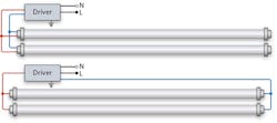
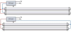
The second scenario has one component - a lamp with an integrated line-voltage driver - and requires very little rewiring (Fig. 2). The installer need only remove the ballast and directly connect line voltage to the existing sockets, then plug the TLED into the sockets.
ballast and connect line voltage directly to the existing sockets, then plug in a
TLED with an integrated line-voltage driver.
But, in the future, an installer may be unaware that the wiring was changed and may plug a fluorescent bulb into the socket - in which case, the line voltage will overload the lamp and may pose a safety issue. Installers who choose to implement Scenario 2 are required by code to educate future users by installing an informational sticker that clearly indicates fixture wiring is non-standard.
This scenario also increases labor costs, as changes must be made to the line-voltage wiring, and existing sockets may need to be replaced.
TLEDs supplied with dedicated LED drivers (UL Type C)
The third option involves a TLED retrofit kit consisting of LED drivers, LED lamps, and labels that have been tested to meet the requirements of UL 1598C. The installer removes the existing fluorescent lamps and ballast, then wires in the new LED driver (Fig. 3).
new LED driver along with installing TLEDs and removing the fluorescent
ballast, the UL Type C TLED retrofit scenario ensures compatibility
of all components of the system.
The third scenario is a certified, reliable solution where all the supplied components have already been tested together as a system. The lamp remains low voltage, eliminating the risks associated with line-voltage sockets. It is also possible to add dimming capability by using a dimmable LED driver and a compatible control system.
The risk in using the retrofit kit is that if existing control wires are not already run to the fixture (such as Lutron EcoSystem or 0-10V wires), adding a dimmable LED driver may be more complicated than a non-dimmable driver.
Scenario 3 is labor intensive but offers predictable, warrantied performance, and the driver/control compatibility can be confirmed in advance.
Consider TLED tradeoffs and performance characteristics
If the application will benefit from high-performance LED dimming, the best practice may be to install LED fixtures with a control system that has been fully tested with the selected fixtures, and is guaranteed to deliver high-performance dimming, energy savings, and a comfortable light environment. Tools such as the Lutron High Performance Fixture List (lutron.com/findafixture) can help inform the selection process.
If you decide to use a TLED retrofit, it is important to consider efficiency, optical quality, product lifetime, and dimming needs.
Each scenario presents different tradeoffs for the overall efficiency of the system. In Scenario 1, the ballast must convert the line voltage to a regulated current and voltage. The electronics in the lamp then must re-regulate the current and voltage specifically for the LEDs.
This double-regulation creates additional losses in the system as compared with Scenarios 2 and 3. In some situations, TLEDs will have to simulate the filaments in the ends of a fluorescent lamp, which often causes additional losses and decreases in efficiency. Scenarios 2 and 3, which use dedicated LED drivers, will typically provide higher system efficiency.
In a new construction or major renovation project, the design team takes great care to ensure the selected luminaires provide adequate lighting for the space. The photometrics of various fixture types and manufacturers are analyzed and compared to determine the best solution for the space.
In all three TLED scenarios, the difference in optical characteristics between LEDs and fluorescents is an area of common concern. Most LED tubes do not have a light distribution pattern that matches fluorescent lamps. Specifically, most TLEDs do not emit light in an even 360° pattern as fluorescents do, and some TLEDs have a beam pattern as low as 105°. This may cause fixtures using these lamps to disperse light differently, or to alter the amount of light available in the space or on desired horizontal and vertical surfaces.
The existing fixture reflector is specifically designed to use light from all outgoing angles of a fluorescent lamp to throw an even illuminance below the fixture. Replacing the fluorescent lamp with a TLED, which is not omnidirectional, can cause the illuminance distribution to become uneven, which in turn can create nonuniformity on the work surface.
TLEDs are often designed to provide a similar number of lumens out of the fixture but out of a smaller aperture. This typically results in more concentrated luminance and possibly creates glare for the occupants of the space. To determine how a particular TLED design will affect lighting levels, a 2014 independent study conducted by the DOE reviewed various TLED designs in combination with several different styles of fixtures. The study concluded that the only way to accurately predict resulting light levels is to individually test each TLED with each fixture.
Finally, some lesser-quality LED drivers (whether integral or external) can cause flicker that didn't exist when fluorescent lamps were used. Because LEDs change their light output very rapidly in response to any changes in input current, any power fluctuations caused by a driver will result in visible fluctuations in the light output (flicker). Lesser-quality drivers can also be prone to "passing-through" normal power line disturbances, which are present in many commercial installations, and can manifest as flicker or shimmer.
In many Scenario 1 situations, a TLED is used with a ballast that has already been installed for a significant portion of its expected life. If the ballast is not replaced at the same time as the TLED is being installed, the benefit of adding that long-life LED lamp is reduced from a maintenance standpoint. If the ballast fails before the lamp's expected end-of-life, facilities personnel will have to get back up on a ladder, remove the lamps, remove the ballast housing, and then replace the ballast. If a new ballast (or driver in Scenario 3) is installed at the same time as the LED lamp, there should be no problem with system life, and maintenance costs are generally reduced over the lifetime of the fixture.
Dimming TLED
Also common with Scenario 1 retrofits, the installed fluorescent ballast is a switching ballast. Many TLEDs support dimming, but the benefit of dimming (which further reduces energy costs and can support task-appropriate light levels) cannot be achieved unless the existing ballast is changed to an LED driver. Today's building energy codes are compelling the adoption of energy-saving controls, as well as including mandates for occupancy/vacancy sensing, and daylight harvesting (see lutron.com/energycodes for more details). Sensor controls generally save even more energy and enhance occupant comfort when dimming is available. In some cases, dimming is required by code.
TLEDs can significantly alter the amount of light in a space, which may lead to uneven light levels, different distribution patterns on walls, and even glare. You can learn more about these effects in a DOE Lighting Facts sheet on upgrading troffers to LEDs. Having the capability to dim the TLED down to the appropriate light output may mitigate these factors while increasing energy savings.
Not all LED dimming options are created equal. Customers are conditioned to expect high-performance, flicker-free, continuous dimming of fluorescent and incandescent lighting to 10% or less. Poor-quality dimmable drivers, or incompatibility of controls, can lead to flicker and unreliable dimming and possibly premature driver, ballast, or control failure. Proper product selection and matching of the LED driver, LED lamps, and controls for your application is crucial to optimal performance.
Switching TLEDs
Most of today's electronic ballasts comply with NEMA 410, which stipulates the maximum amount of inrush current that an electronic device, such as a ballast or driver, can draw. Complying with this industry standard ensures that turning the load on and off will not cause any unnecessary stress to the switching control, and will never cause false tripping of circuit breakers.
Many LED drivers (including those used internal to or external from TLEDs, as in Scenarios 2 and 3) do not meet NEMA 410 standards. So, despite their lower wattage, LED drivers may cause undue stress on switching controls, leading to potential welding of the switch contacts and failure of the control. In extreme situations, heavily-loaded circuits that turn on simultaneously (such as the situation after a power failure) may cause nuisance tripping of a circuit breaker. As an installer or customer, insist that TLED products that use internal or external LED drivers comply with NEMA 410 inrush current limits.
Conclusion
Choosing a TLED retrofit solution is a careful balance - ease of installation versus cost versus performance. Even beyond performance, safety is the overriding factor in any electrically-based operation. For optimal performance and the highest level of safety, the use of a pre-certified solution consisting of a dedicated LED driver with low-voltage TLEDs (Scenario 3) is recommended for most TLED retrofits.
ETHAN BIERY is LED engineer leader at Lutron Electronics (lutron.com).
Links
LEDs Magazine has examined the application of TLEDs - also called LED tubes and T8s - as their popularity has grown due to the large number of commercial and institutional buildings that rely on such linear light fixtures.
How do plug-and-play T8s stack up against ballast-bypass LED lamps?
LED tubes approach mainstream adoption despite complexities
Hands-on testing of popular LED T8 lamps and linear fixtures reveals promises and pitfalls


