Horticultural SSL fixtures face a daunting environmental challenge. TODD PHILLIPS explains the basics of circuit protection for such product developments and regulatory testing requirements.
Indoor farming is quickly becoming a growth industry, especially with the advent of LED-based horticultural lighting. One factor driving this growth is likely the rapid decrease in the amount of arable land available for traditional agriculture. According to the United Nations’ Food and Agriculture Organization, the amount of arable land per person around the world is shrinking at an alarming rate, decreasing from 0.38 hectare in 1970 to 0.23 hectare in 2000, with a projected decline to just 0.15 hectare per person by 2050. As a result, more fruit, vegetable, and flower growers are turning to indoor horticulture for reasons ranging from a desire to bring the field closer to the table, to farm more sustainably on less real estate using fewer resources, to allow for a year-round growing season, or simply to raise crops that otherwise couldn’t flourish in a particular climate. But developers working on LED-based horticultural fixtures must take steps to ensure reliable operation in a potentially harshenvironment.
Indeed, keeping crops growing indoors year-round demands reliable lighting systems. In the past, such lighting typically involved high-pressure sodium (HPS) lamps. Although originally used for lighting streets, parking lots, and security areas, HPS lamps have often been used in indoor farms because they deliver high light intensities in the 565–700-nm wavelength range, which supports photosynthesis. For horticultural applications today, evolving solid-state lighting (SSL) offers many advantages over HPS lamps — starting with energy efficiency.
SSL advantages and challenges
There are other advantages to LED lighting. It’s easy to control both in terms of on-off cycles and dimming, and in spectrum. What’s more, LED lamps feature long operating lifespans (more than 50,000 hours) that speed up payback and reduce maintenance costs.
Still, lighting system developers seeking to take advantage of the growing demand for products suitable for indoor agriculture must be aware that LEDs aren’t as robust in terms of withstanding electrical disturbances as HPS lamps. Hazardous conditions that affect horticultural lighting can be the result of environmental factors such as heat and humidity, in addition to the typical disturbances that can negatively impact any electrical system, namely power faults and switching load surges.
Unlike many general lighting applications, LED lighting systems designed for plant growth are usually intended to operate continuously to maximize annual crop yields. In addition, the operating environment is often very humid, and electronics may be subject to chemical, biological, or other types ofcorrosion.
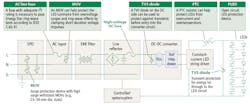
FIG. 1. The typical LED luminaire driver circuit depicted includes transient- and surge-energy protection devices.
Horticultural applications
Indoor farming can involve a wide variety of growing systems and facility types, including everything from purpose-built indoor vertical farms to recycled shipping containers, as well as growing systems ranging from hydroponics to cultivating plants traditionally in soil in standardized containers. LED lighting for horticulture takes a variety of form factors, depending on the type of plants grown and the structure of the growing environment. These form factors include LED strings, LED arrays, flowering lamps, or linear LED lamps (also known as TLEDs).
Lighting control electronics (for timing and power) are typically located inside a wall-mounted enclosure. The entire control circuit must be protected from transients — from the LED to the passive and active components upstream. Providing protection from transients for both the LEDs and all the active and passive components upstream from them in the circuit is one of the most significant challenges associated with indoor LEDluminaires.
Any electrical component directly connected to an AC power source can be damaged by short-circuit and overload conditions caused by component and/or circuit failures inside the luminaire. In addition, lightning surges or load-switching transients (originating outside the luminaire) can create voltage spikes or ring waves that can stress and ultimately damage components inside theluminaire.
LED luminaire circuit blocks
To understand the circuit protection problem, let’s consider a typical driver circuit. Fig. 1 details a driver circuit for LED-based lights, breaking the functionality into the basic circuit blocks shown in the figure with AC power entering on the left and ultimately powering the LEDs located on the right. Working from right to left in the figure, we have:
- Multiple, single-chip LEDs configured in series electrically, known as an LED string. Open LED protector devices (PLEDs) are often used to prevent the entire string of LEDs from turning off in the event that one LED fails open. Multiple strings are often connected in parallel and driven by a common power source.
- An LED string driver circuit, with corresponding controller circuitry for LED string protection, including a series positive temperature coefficient (PTC) resistor for overcurrent protection (OCP) and a parallel transient voltage suppression (TVS) diode for overvoltage protection (OVP).
- A DC-DC converter circuit, which would include a parallel TVS diode on the input as secondary OVP for the downstreamcomponents.
- A line rectifier circuit, which would include a series high-voltage DC fuse on the output for secondary OCP of downstreamcomponents.
- Electromagnetic interference (EMI) filtercomponents.
- An AC input circuit, which is made up of a line series AC fuse and a line-to-neutral parallel metal oxide varistor (MOV).
Circuit operation
The primary overcurrent protection device for an LED luminaire is located at the AC input. When properly sized and selected, an AC fuse in series with the AC line will adequately defend all downstream components from induced transients, overloads, and short circuits by safely disconnecting all circuitry from the AC line input.
A fuse is designed to be the intentional weak link in an electrical circuit, providing protection by reliably and predictably melting during short circuits and other current overload conditions. An AC fuse with an adequate I2t rating is necessary to pass applicable surge testing as described by standards such as the Energy Star ring-wave tests or according to IEEE C.62.41. The nominal melting I2t rating, which is expressed in ampere squared seconds (A2sec), specifies the amount of energy required to melt the fusing element.
Often, selecting a fuse based on the nominal melting I2t is meant for applications in which the fuse must endure multiple large current pulses of short duration. Different fuse constructions may not react the same way to a surge, even if their nominal melting I2t rating exceeds that of the waveform energy. For example, electrical surge pulses produce thermal cycling that can fatigue the fuse mechanically and shorten its life.
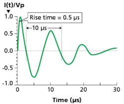
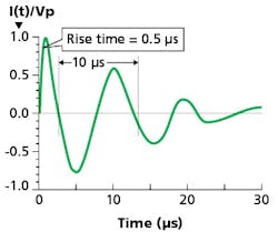
FIG. 2. Energy Star defines a transient voltage immunity test waveform: 0.5-μs rise time × 10-μs duration (100-kHz) ring wave.
Selecting a fuse
Designers of LED-based lighting systems for horticulture must consider a variety of important issues in order to select an appropriate AC input circuit fuse, including thefollowing:
- The first step is finding the answers to a number of technical questions about the application. These questions include the luminaire’s normal operating current; application voltage; ambient temperature; overload current level and length of time within which the fuse must open; maximum allowable fault current; and the pulses, surge currents, inrush currents, start-up currents, and circuit transients, etc.
- It’s vital to understand early in the design process the region in which the luminaire will be used. Depending on whether the luminaire is intended for use in the United States, elsewhere in North America, Europe, Asia, or somewhere else, different standards will govern design and testing requirements. For tips on understanding the agency approvals and certifications required based on geography, see the section further along in this article that addresses testingstandards.
- LED-based luminaires have tight space constraints. Determine the size limitations that might affect the fuse that can be used. Fuses can be packaged using a variety of methods, but surface-mount designs are the most common form factor for LED lighting applications. Fortunately for circuit designers, smaller-footprint fuses are now available to protect the AC input, some just half the size of the smallest fuses previouslyavailable.
- Consider the ambient temperature where the fuse will operate. For ambient temperatures around 25°C, it’s generally recommended that fuses be operated at no more than 75% of their nominal current rating for UL-rated fuses, and 100% of their nominal current rating for IEC-rated fuses. Fuses are essentially temperature-sensitive devices, so even small variations in temperature can greatly affect the predicted life of a fuse when it is loaded to its nominal value, usually expressed as 100% of the rating. A derating of the fuse current rating may be necessary for fuses operated in elevated ambient temperature environments. Fuse manufacturers provide temperature derating curves for this exact purpose.
- Determine the application’s required electrical breaking capacity. Often this is referred to as the interrupting rating or short-circuit rating. It is defined as the maximum current that the fuse can safely interrupt at the rated voltage. During a fault or short circuit condition, a fuse may experience instantaneous overload current that is many times greater than its normal operating current. Safe operation requires that the fuse remain intact (no explosion or body rupture) and clear the circuit.
- Be sure to allow sufficient time for thorough environmental testing, application testing, and verification prior to production. This will ensure the safe operation of the LED power system design in an actual growingenvironment.
Transient protection strategies
For an LED-based light, the primary overvoltage protection device is an MOV located on the AC input circuit. It will clamp short-duration voltage pulses, and when properly selected for all the design parameters, help protect downstream components from electrical overstress (EOS) damage caused by ring-wave effects and induced transients. MOVs offer a cost-effective way to minimize transient energy that could otherwise make its way into downstream components. Proper MOV selection is based on a number of electrical parameters, including the voltage rating, peak pulse current, energy rating, disc size, and leadconfiguration.
Select an MOV based on the following importantparameters:
- Reverse standoff voltage (VR) — This is arguably the most important parameter. The VR of the TVS diode must be equal to or greater than the peak operating voltage of the circuit (or the specific part of the circuit) that the TVS diode is supposed to protect. This is needed to avoid having the TVS diode clip the circuit drive voltage.
- Peak pulse current (IPP) — The IPP is the maximum current that the TVS diode can withstand without suffering damage. Typically, it is stated in the specs with reference to an exponential waveform (e.g., 10×1000 μs). Divide the peak transient voltage by the source impedance to determine the required IPP.
- Maximum clamping voltage (VC) — The VC is the peak voltage that will appear across the TVS device when it is subjected to the IPP, based on the referenced exponential waveform.
- In indoor farming applications, transients might be the result of lightning-induced surges on the AC input, switching surges, power faults, ESD events, or moisture intrusion due to high humidity or irrigation. There will be instances when a specific LED luminaire’s operational circuitry is just not able to survive the required transient event levels, even with surge protection used at the AC input. In these cases, adding a secondary TVS diode for overvoltage protection is a proven solution that further clamps the “let through” energy from the MOV. For the most extreme cases, a high-voltage DC fuse (as shown in the center of Fig. 1) can be used for DC link overcurrent protection for the LED driver.
Additional types of protection
To ensure the reliability and robustness of LED strings, adding polymeric positive temperature coefficient (PPTC) resettable devices in series with the LED is a good strategy to use to prevent thermal runaway.
In addition, a PLED will protect the reliability of an LED string. If an LED in a string fails because of a surge, then all the LEDs downstream will go dark. Many designers add a PLED in parallel with each LED, so in the event that a single LED fails (LEDs typically fail open), the PLED shunts the current around it, keeping the rest of the stringilluminated.
Can your design live up to the standards?
As mentioned earlier, development teams must make sure their designs can meet standards in various geographies in addition to developing a robust circuit. Various regulatory organizations around the world have established a number of test standards that provide clear guidelines for manufacturers to follow when designing, manufacturing, and testing indoor LED bulbs, fixtures, and luminaires. Here are a few notes on some of the most important ones.
UL 8750 (Standard for Safety of LED Equipment for use in Lighting Products) requires the design to use a protective device that will interrupt or limit the flow of current in the event of an overload, in order to minimize the risk of fire and shock. For this type of application, a fuse is the most reliable and commonly used technology to protect against short circuit or overload events.
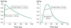
FIG. 3. The IEC 61000-4-5 standard defines surge immunity test waveforms: 1.2×50-μs open circuit voltage and 8×20-μs short circuit current.
In the United States, bulb manufacturers must comply with Energy Star transient voltage surge specifications for LED replacement bulb assemblies used in residential and certain commercial applications. For example, Version 1.4 of the Energy Star program requirements defines a 0.5-µs, 100-kHz ring wave transient test (as illustrated in Fig. 2) for integral LED lamps. Other test requirements include a test level of 2.5 kV/83 A, line-to-line (ANSI/IEEEC.62.41-1991, Class A [i.e., indoors] operation) and the ability to withstand seven strikes in common mode and seven in differential mode, with one minute between each strike.
In countries other than the United States, the IEC/EN 61347 LED driver (power supply) specification and IEC/EN 62031 for LED arrays/modules contain safety requirements for these power supplies.
IEC 61000-4-5 is used throughout many countries. It is a surge standard often used for LED lighting assemblies. In addition, part of IEC 61547, “Equipment for General Lighting Purposes” requires EMC immunity testing. Fig. 3 shows two waveforms that define the rise time and duration of the test voltage and current.
Additional test requirements include thefollowing:
- For self-ballasted lamps and luminaires lower than 25W, 500V/250A: Apply 500V line-to-line with 2Ω source impedance and 1 kV line-to-ground with 12Ωimpedance.
- For luminaires higher than 25W, 1000V/500A: Apply 1 kV line-to-line with 2Ω source impedance and 2 kV line-to-ground with 12Ωimpedance.
- Ten strikes, 5+ and 5- at phase angles 90°/270°, with one minute between each strike.
Conclusion
The ongoing expansion of the indoor farming market means that lighting design engineers need to educate themselves about how to protect the LEDs that will be an essential part of this industry. Circuit protection device manufacturers are an excellent source of guidance on the various fuse, MOV, and TVS diode options available and how to apply them.
TODD PHILLIPS is global marketing manager at Littlefuse, focusing on the LED, datacenter, and mobile markets. He joined Littelfuse as a sales engineer in 2006 for the industrial industrial business unit. Phillips joined the electronics business unit in 2011 as a regional sales manager. His current responsibilities include development of marketing collateral material, management of marketing activities for new product launches, and performing market studies and feasibility analyses for new product ideas. Phillips has presented at the 2018 IES Street & Area Lighting Conference and has appeared in thought leadership videos for Littelfuse. He received his BSEE from Milwaukee School of Engineering.
