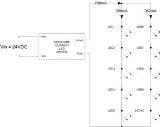
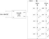
A typical high power 350mA white LED has a forward voltage (Vf) of about 3.3V, so if an cluster of 10 LEDs were required in an application, connecting of the LEDs all in series would require a driver capable of delivering at least 33V. If the supply voltage is 24VDC, then an expensive boost converter would be required with all the attendant EMC problems it creates.
The basic assumption made with this circuit suggestion is that the 700mA regulated current from the LED driver will be shared approximately evenly across both strings of LEDs, i.e. each string of LEDs will see 350mA of current. However, this is rarely the case.
How LEDs become overdriven
Even if the LEDs are all from the same production batch and sequentially manufactured, the Vf of individual LEDs still has a ±20% tolerance. The tolerances mean that the total forward voltage for each string can be very different and therefore the current mismatch significant (see Fig. 2).
Worse, as the LEDs started to get warm, the combined forward voltage of the higher current string started to decrease. This increased the imbalance and more current started to flow through the already over‐driven string. The current through the other string of LEDs reduced as the constant current driver compensated, so they started to cool down and their forward voltage increased.
The net result was thermal runaway with the majority of current flowing through one string only, even though the LEDs were mounted on a large metal heat sink. The test was stopped when the current imbalance was 600mA to 100mA. Obviously, if this situation was allowed to continue, the over‐driven string would eventually fail and then the entire 700mA would flow through the remaining intact string and destroy that as well.
And this circuit is often given as a recommended application example!
Using a current mirror
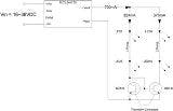
What is required is a way of balancing the currents flowing through the two strings to ensure that they remain approximately equal, even if the combined forward voltages are mismatched. The balancing circuit must also continually compensate for changes in forward voltage caused by changes in the operating temperature and by aging of the LEDs.
In tests using Recom’s 700mA LED driver and two strings of 350mA Osram LEDs, the currents flowing through the two strings were matched to an accuracy of about 87% over the entire input voltage range of the driver from 16VDC to 36VDC. The LED currents were stable as the LEDs warmed up and no thermal runaway was observed. It is important that the two transistors are both at the same temperature so a copper clamp was used to thermally connect both transistors together to keep their Vbe voltages stable.
In addition, if any of the LEDs in String 1 fail, the current to ALL of the LEDs is disconnected. Thus the LEDs on String 2 are automatically protected against being over‐driven.
However, this circuit is still not ideal. The currents are not perfectly matched and if any of the LEDs in String 2 fail, then all of the 700mA source current will still flow through the first string and destroy it.
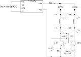
Over-current protectionFig. 4 shows the final version of the current balancing circuit. The addition of 1.5 Ohm resistors in the emitter paths makes the circuit less sensitive to small Vbe changes and balances the currents in the two strings to 99% accuracy.The addition of a small signal transistor as a current monitor protects the LEDs from being overdriven in the case of any LED failures. If LED1‐LED5 fail open circuit, then the current in the second string falls to zero as before. However, if LED6–LED10 fail, then the current increases in the first string until the voltage developed across the 1.5 Ohm emitter resistor reaches around 0.7V, thus turning on the BC337 transistor and pulling the base voltage of the power transistor to ground and limiting the current. With the component values given in the circuit, the measured current limit was 445mA with String 2 open circuit.
The circuit suggestion given in Fig. 4 can theoretically be extended to any number of LED strings by adding an NPN transistor and emitter resistor to each additional string and tying the transistor bases together. The current flowing through the reference transistor will be faithfully mirrored by all of the other transistors.
However, considering that LEDs are high reliability illumination sources and the driver and associated components need to be equally reliable to get the maximum lifetime out of the system, it is recommended that the circuitry be kept as simple as possible and restricted to only one or two strings per driver.
