While photodetectors have long been used alongside goniometers to characterize light sources, PASI MANNINEN and MIKOLAJ PRZYBYLA explain that a goniospectrometer system enables collection of a more robust set of parametric data for LED-based products.
Goniometers are a class of optical test instrument with mechanics that allow characterization of a light source for every angle, and such test equipment is widely used with LEDs and solid-state lighting (SSL) products. In most instances, goniophotometers with a photodetector were the primarily available systems for measuring light intensity. However, to measure properties like angle-dependent luminous intensity along with colorimetric values like color coordinates, correlated color temperature (CCT), and CRI of LED-based luminaires, a goniospectrometer better meets the requirements of accurate and complete characterization. This article will explain how goniometers work, considerations for accurate measurements, and the latest options available for photometric measurements.
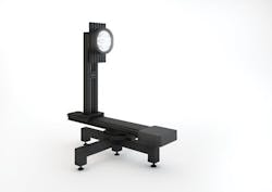
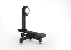
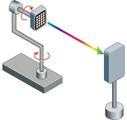
FIG. 1. A spectral measurement device such as a goniospectrometer delivers increased accuracy for LED-based luminaire testing, providing complete characterization of LED sources.
A goniometer (Fig. 1) is an instrument with a rotating axis used for the measurement of luminous flux and the luminous intensity distribution of a luminaire or light source. The luminous intensity can be obtained through illuminance (far-field) or luminance (near-field) measurements at a fixed distance from a luminaire rotated in various directions. With sufficient angular step and range, the luminous flux of a luminaire can be calculated by summing up all the luminous intensities from each measurement direction. From the luminous intensity distribution, it's possible to deduce lighting application properties like transversal/longitudinal isolux curves or cone diagrams.
Types of goniometers
The luminous intensity distribution of lamps and luminaires is measured on different planes. The number of distribution curves for luminous intensity and the selection of specific measuring planes depend on the light source, the goniometer type, and the number of luminous intensity distribution curves. CIE Publication Number 70 differentiates between the 1, 2, and 3 goniometer types. These goniometer types are also frequently referred to by their measuring planes: A, B or C.
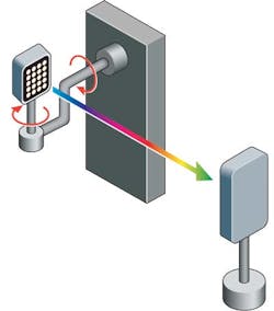
The Type A goniometer (Fig. 2) features a fixed horizontal axis and a moving axis perpendicular to the first axis. Measurements are taken by rotating the light source about the horizontal axis, while keeping the other axis in a fixed position (rotation versus elevation). Type A goniometers are a good choice for characterizing automotive lighting with a relatively limited beam.
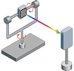
Type B goniometers (Fig. 3) have a fixed vertical axis and a moving horizontal axis. Measurements are taken by rotating the light source about the vertical axis, while keeping the other axis in a fixed position (elevation versus rotation). The type B is suitable for displays and floodlights.
The Type C goniometer (Fig. 4) is a highly specialized type, featuring a fixed vertical axis and moving horizontal axis. Measurements are made on the C-plane or on conical surfaces. The Type C goniometer is the same as the Type B, with the difference that the light source is rotated by 90°. International standards recommend this type for general lighting systems.
Source orientation
Ultimately, however, any light source in question must be characterized in a way that provides data critical to the application at hand and relative to the operational characteristics of the source. Traditional light sources like fluorescent tubes or sodium lamps have very specific requirements in terms of burning position. Any change in the position results in a significant drop of luminous flux emission. This is due to the fact that any change in position affects the distribution of heat and gas molecules inside the bulb.
A goniometric measurement of SSL sources (LEDs and OLEDs) is more straightforward as far as burning position is concerned. SSL-based products and therefore their components do not change characteristics based on orientation. SSL luminaire design may have a small effect on the results as the thermal management can change a bit with orientation. The magnitude of this effect depends on the shape and type of the SSL luminaire heat sink, as well as the type of goniometer.
FIG. 2. Type A goniometers rotate a light source around a fixed horizontal axis, allowing a detector at a fixed distance to capture intensity measurements.
Depending on the shape and size of the heat transfer radiator (for example, a heat sink), the distribution of heat energy may change when the luminaire is rotated. Higher temperatures on the thermal interface to an SSL source lead to lower LED luminous flux. On the other hand, time constants are often quite long (depending on the heat sink) to ensure that the results do not change during a short goniometric scan.
The rotating speed experienced by an SSL luminaire under test also has an influence on the convective heat transfer. In Type C goniometers intended to produce C gamma photometric diagrams, which again are recommended for general lighting applications, this effect is very limited since the rotation speed is very low.
What is a suitable detector?
The mechanical movements are only part of the story of a goniometric system. Such a system also requires the measurement element that is located a fixed distance from the light source under test. Options include a photometer and a spectrometer.
FIG. 3. A Type B goniometer rotates a light source around a fixed vertical axis and is useful in making measurements on displays and floodlights.
Luminous intensity measurements are typically made with a broadband photometer instead of a spectrometer. A photometer can accurately measure intensity quickly and at low light levels. Typically, a spectrometer has limited sensitivity that affects measurement time length stretching the characterization time generally. Moreover, the measurement time advantage of a photometer is even more significant with the low signal conditions that result from low light levels. But we must keep in mind that a photometer will only provide intensity levels (cd), while a spectrometer can simultaneously make angle-dependent measurements of color, CCT, and CRI.
When a photometer is suitable for the test at hand, there are still some guidelines that will yield optimum results. The photometer needs to have a good match with the photopic spectral sensitivity (V(Λ)) defined by the CIE1924 standard describing human eye sensitivity as described by the spectral quality factor f1´. Part 7 of the DIN 5032 standard addresses the sensitivity match by prescribing four device classes: Class L, Class A, Class B, and Class C, with Class L as the tightest match, specified using 15 performance criteria. The f1´ factor defines how well a light measurement device matches the V(Λ) curve. Laboratory Class L photometers (f1´<1.5%) and Class A photometers (f1´ <3%) are generally considered as sufficient in terms of performance for goniometric measurements.
Spectral mismatch
Still, the issue is even more complex. The f1´ value does not provide the actual luminous intensity measurement errors caused by a spectral mismatch, because it depends on the spectrum of the light source to be measured and the spectral shape of the mismatch. It is worth noting that the uncorrected measurement errors from a Class A photometer can be smaller than those from a Class L photometer, and even the maximum error deviation for a group of LED spectra within a typical CCT/CRI range can be smaller for practical Class A photometers in comparison to Class L meters.
FIG. 4. Recommended for characterizing general lighting products, the Type C goniometer is a specialized version of the Type B that makes measurements on the so-called C-plane.
LED light sources can be measured reliably using a high-quality goniophotometer. A spectral mismatch correction should be characterized for a goniophotometric measurement of single-color LED light sources or the relative luminous intensity distribution could be also scaled by an absolute measurement with an integrating sphere spectrometer. To apply such a correction, the measurement device needs to be evaluated and a correction file must be applied to obtain accurate results. This should be provided by the device manufacturer. Another method would be to compare the results between the sphere measurement and the goniometric measurement as described in the IES LM-79 standard.
When using a spectrometer as a detector together with a goniometer (goniospectrometer), the spatial color uniformity of a luminaire can be directly measured. The goniospectrometer measures color coordinates, CCT, and CRI as a function of observation angle, and the goniospectrometer software further analyzes the SDCM (standard deviation of color matching) value corresponding to the MacAdam ellipse within which the color coordinates from different directions are located. Using a high-precision spectrometer, the luminous intensity distribution, luminous flux, and wall-plug efficiency of a luminaire can be measured as well.
Optimal measurement setup
Goniospectrometer systems use a spectroradiometer placed at a certain distance from the luminaire that conducts a set of measurements while the goniometer arm moves the luminaire. Such an instrument can measure the spatial distribution of all relevant photometric quantities (E = illumination [lx], I = intensity [cd], CCT, CRI, peak wavelength, etc.) concurrently. The CRI can only be measured with a spectroradiometer. In such a test setup, the total luminous flux is obtained by numerical integration.
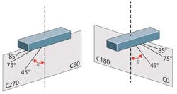
FIG. 5. For C-gamma test, the goniometer is used to test each of four C-planes at prescribed gamma angle intervals.
A goniometric measurement room should feature black surfaces with screening apertures as needed to reduce stray light. The required laboratory room size depends on the selected goniometer type. The SSL luminaire or fixture is mounted to the goniometer in such a way that the turning axes cross its photometric center and the luminaire axis is parallel to the optical axis. The measurement distance between the photometer and goniometer needs to be at least five times longer than the longest transverse dimension of the Lambertian source to obtain sufficient measurement accuracy. For a more directional source, the distance should be longer.
Standards for luminaire measurements
The United States standard "IESNA LM-79-08 Approved Method: Electrical and Photometric Measurements of Solid-State Lighting Products" and the European Union standard "Draft, EN 13032-4 Lighting Applications - Measurement and presentation of photometric data of lamps and luminaires - Part 4: LED lamps, modules and luminaires (joint work with CIE TC2-71)" both require goniometers for the full characterization of lamps and luminaires. The requirements call for measurements using an integrating sphere, as well as goniometric measurements.
These standards also recommend the use of spectroradiometer systems and require Type C goniometers to be used for the evaluation of lamps and luminaires. Again, such goniometers allow evaluation of the light source for each of the four C-planes (Fig. 5). Moreover, for each C-plane testing proceeds with a mechanical adjustment, producing a prescribed gamma angle between each measurement - thus the term C-gamma. During goniometric measurement, the luminaire is set at each of these positions, and for each position the intensity value is calculated.
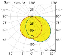
FIG. 6. A C-gamma polar diagram depicts the intensity values at different gamma angles.
The result of such testing is a C-gamma polar diagram such as the one shown in Fig. 6. This polar representation is a typical diagram used to illustrate how light is distributed in space. Again, the C-planes and gamma angles are indicated and the curve shows the signal level in each specific position.
Goniospectrometric measurements are a crucial step in evaluating SSL luminaires. Companies such as GL Optic now offer goniospectrometer systems that can be easily applied in such test and measurement tasks. The results of such testing confirm LED-based luminaire performance and provide information with regard to light distribution.
Spectral measurement devices ensure increased accuracy for LED-based luminaire testing, providing colorimetric data such as color, CCT, CRI, and much more. Since the color and intensity of LED lighting change depending on the viewing angle, this testing method is critical to successfully evaluating SSL products and providing the necessary data for designers, installers, and end users to both develop and select high-performance luminaires.
PASI MANNINEN is a goniometric systems engineer, and MIKOLAJ PRZYBYLA is COO at GL Optic (gloptic.com).
