LED lighting is becoming widely adopted and is displacing most traditional lighting technologies. However, the traditional methods used to control light sources have not been similarly displaced. In an effort to address some of the long-standing weaknesses of one of the most-popular control methods, the National Electrical Manufacturers Association (NEMA) recently released the ANSI C137.1-2019 standard for 0–10V control of LED drivers and fluorescent ballasts. The new standard builds upon previous specifications by providing requirements for some aspects of dimming-curve shape and endpoints. In order to characterize the performance variation found in market-available LED drivers, and to explore the potential impact of ANSI C137.1, Pacific Northwest National Laboratory (PNNL)’s Connected Lighting Test Bed was used to evaluate the response to 0–10V controls signals of 21 different LED outdoor cobrahead luminaires (typically used for street-lighting applications) that claimed dimmability via a 0–10V interface. The results provide insights about how ANSI C137.1 will affect the performance variation currently found among such products.
And now for something completely different
Lighting systems have historically utilized either a proprietary control method or one of a handful of standardized methods (e.g., 0–10V, DALI, and DMX512). The utility and market success of the standardized methods have been limited, for a variety of reasons. In some cases, performance aspects that are key to meeting lighting-design goals are not covered by a standard, leading to varying product implementations that can yield unpredictable and unsatisfying results. Compliance-testing tools and processes for the standardized methods have not been available or mandated for most of their existence, and as a result, manufacturer interpretations of the standard methods have varied — in some cases unintentionally, in other cases as part of a business strategy to differentiate from competitors. These varying implementations and interpretations can result in specification and commissioning challenges that range from a lack of interoperability to difficult-to-predict performance. One performance aspect that has long been difficult to predict is the dimming response of a lighting device — or, more specifically, the relationship between the user interface or control setting and the lamp or luminaire’s light output.
Dimming-curve variations can have wide-ranging detrimental effects on a lighting installation. In indoor environments, a designer might specify luminaires from different manufacturers and develop a controls narrative that requires those luminaires to dim to the same level to create a particular ambient effect, only to find that they dim to different levels — thereby producing unintended non-uniformity. In outdoor environments, a municipality might desire to moderately dim its residential lighting in the middle of the night to save energy, only to find that the luminaires are not dimming at all — thereby not saving any energy — and perhaps drawing the incorrect conclusion that the wireless control system has failed or is not functioning correctly.
While the Digital Illumination Interface Alliance introduced a certification program in 2017 for the recently released DALI-2 specification, which improved interoperability and led to more-predictable performance among certified products, this has not led to widespread adoption of DALI by the lighting industry. The 0–10V methods have long been popular, due to their simplicity and low cost of implementation, and 0–10V methods are presently the most commonly-available control interface for indoor and outdoor LED products in North America.
The products we tested all had ANSI C136.41-compliant receptacles, but varied by luminaire as well as by LED driver manufacturer and maximum power draw. Most (20 of the 21) products claimed a dimming range of 10–100%, while one claimed a range of only 30–100%. One sample was tested for the products with a 10–100% dimming range, while three samples of the product with the 30–100% dimming range were procured and evaluated in order to investigate variation within a given make/model. The 21 products comprised 14 different luminaire manufacturers and eight different driver manufacturers. All eight driver manufacturers claimed a linear dimming curve. The 0–10V control signal was delivered via the ANSI C136.41-compliant receptacles, and luminaire power draw was measured at varying control signal settings. While luminaire light output was not measured, it is well-known that the relationship between power and light output (i.e., luminous flux) is linear and monotonic for LED light sources over most of their output range.
A wide variation in performance
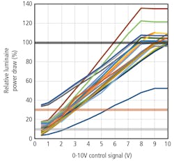
Variation in the dimming curves plotted from the relative luminaire power draw for different luminaires was significant, as shown in Fig. 1. Most of the luminaires did not utilize the whole 0–10V control voltage range and showed a dead band above 8V and below 1V. One luminaire reached only 55% of its rated maximum power, while another went up to almost 140% of its rated maximum power at a 10V control signal. The variation in relative luminaire power at a given control voltage was greater at higher control voltages.
The relative (to the luminaire manufacturer rating) power draw across all of the luminaires, at a tested control voltage, varied from ~32% (at a control voltage of 0.5V) to ~88% (at a control voltage of 8V), resulting in an average variation across all tested control voltages of ~59%. The variation seen at lower control voltages is the result of different drivers having different minimum rated power, and the variation seen at higher control voltages is the result of different luminaires reaching their maximum power draw at different control voltages (i.e., 8V, 9V, or 10V). Minimum driver-output power as a percentage of maximum output power varied from ~2% to ~28% at a control voltage of 0.5V.
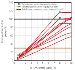
The ANSI C137.1 standard specifies low and high control-voltage targets for LED driver relative output power as 1V and either 8V or 9V. Given that these requirements are for driver-output power as opposed to luminaire power draw, the driver-output power was estimated by multiplying the measured luminaire power draw by the manufacturer-reported driver efficiency. Nine of the 21 drivers were found to be noncompliant with ANSI C137.1 requirements, as shown in Fig. 2. Six of the 21 drivers were found to be noncompliant because they failed to reach maximum output power at 8V or 9V. Three of the 21 drivers were found to be noncompliant because they failed to reach minimum output power (as specified by the manufacturer) at 1V. Three of the 21 drivers were found to be noncompliant because they delivered more power at their high voltage control point than the maximum output power rated by the manufacturer. The relative (to the luminaire manufacturer rating) power draw across the 12 luminaires containing compliant drivers, at a tested control voltage, varied from ~32% (at a control voltage of 0.5V) to ~60% (at a control voltage of 8V), resulting in average of ~47%.
Not a panacea
From this limited testing, it appears that the new ANSI C137.1 standard will indeed have an impact on market-available products and will reduce some of the performance variation they’ve exhibited up till now. However, the new standard will not necessarily result in uniform or predictable performance. The output variation at a given control voltage for compliant products is reduced — from an average of ~59% to ~47% — but remains significant. Notably, while the standard defines a control-voltage target for minimum output power, it does not specify a minimum output power requirement, so luminaire manufacturers will still have to evaluate driver claims independently. Similarly, while the standard defines a control-voltage target for maximum output power, it does not specify a maximum output-power requirement — or, more applicably, a requirement that the maximum luminaire output power is less than or within some bounds of the luminaire manufacturer rating. So, end users might continue to be surprised that their luminaires draw more than their rated power when their 0–10V control is set to full output.
Get to know our experts
MICHAEL POPLAWSKI, ANAY WAGHALE, and SHAT PRATOOMRATANA work at Pacific Northwest National Laboratory (PNNL), where their research efforts are primarily supported by the US Department of Energy (DOE) Lighting R&D Program and focus on characterizing various aspects of emerging connected lighting systems. A more comprehensive reporting of this work, including more test method details and data analysis, will soon be available on the DOE connected lighting system website.
For up-to-the-minute LED and SSL updates, why not follow us on Twitter? You’ll find curated content and commentary, as well as information on industry events, webcasts, and surveys on our LinkedIn Company Page and our Facebook page.


