One of the most frequently used design solutions for LEDs is the total-internal-reflection (TIR) optic. In classical optical design, the designer incorporates lenses to obtain a desired illumination pattern from the LED system. But lenses can only collect light within their diameter; light outside the diameter of lens is lost, resulting in the need for further optics. However, the TIR optic is a single, small part that encompasses the entire light source, reducing or eliminating optical loss. These TIR reflectors can be manufactured in plastic for very low cost.
The design of TIR optics has three different approaches. The first and simplest is to create a TIR lens using standard aspheres, but our preferred method is to use surfaces of revolution based on either free-form curves like cubic splines or Bézier curves. Our primary design tool for these projects has been Zemax software EE.
In the traditional asphere approach the designer specifies the number of aspheric coefficients for creating the desired surface. The disadvantage of this method is that each of the coefficients influences all the points of the generated aspheric surface. Therefore, creating a complex surface means making multiple curves and then connecting them. This surface will not be smooth but have obvious intersections where the curves meet.
A better method for designers is to use an ordinary cubic spline of equally spaced radial points numbered 0 to n along a length z, and then have Zemax sweep the part around to form the solid, or shell. In this case, control points will lay on the curve, eliminating the need to solve nonlinear equations for ray intersections with the surface created by the cubic spline curve. It also means the curve can be smooth.The disadvantage of the cubic spline is that the engineer must join the many small cubic polynomial curves to one big curve to obtain multiple control points as necessary. As with the multisurface asphere, the cubic spline is not a single curve; rather, it is a set of curves. Furthermore in some cases a cubic spline can cause undesired oscillations in the curve.
The Bézier approach remedies these disadvantages. The Bézier curve is named after French engineer Pierre Bézier who used them for describing automobile bodies in the 1960s. Today the animation industry uses them to help create natural looking movement and curves. The Bézier approach is unique because it lets us model a free-form curve; specifically a parametric curve defined by set of control points, P0, P1, … Pn as a function of time t.
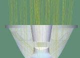
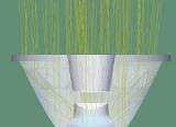
The parametric surface in the Cartesian coordinate system can be easily obtained from the generalized formula for the Bézier curve. In ray tracing, the engineer must find the point where the ray and the surface intersect, as well as the vector normal to the surface at this point. In our work we have found this approach to be powerful and stable (see Fig. 1).
A minor drawback of the Bézier-curve approach is that the control points do not lie on the curve; only the start and end points cross the curve. Furthermore, to use the technique, the engineer needs to solve the set of nonlinear equations to find the point where the ray intersects the revolved Bézier curve.
User-defined DLLs
To address these issues in Zemax, we have devised a method to fix the dimensions of Bézier-based optics. Because Zemax allows user-defined objects in ray tracing, we have created our own object with a dynamic link library (DLL) to facilitate system optimization.
Coefficients of standard aspheres have different influences on the entire surface during optimization; for example, high-order coefficients of standard aspheres have very small values. In Bézier curves the influence is the same, because all control points have an infinitesimal order. Therefore the technique makes it easier to specify the dimensions of the optics compared to the asphere technique.
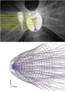
Furthermore, complex objects cannot be modeled with standard aspheres. For example, to model a wine glass containing water, we traced a circular beam of rays so we can see specks of light transmitted through the wine glass (see Fig. 2, top). With standard aspheres creating this type of free-form model is not possible. The user-defined DLL object allows optimizing of multifaceted reflectors based on Bézier splines (see Fig. 2, bottom). The design can be exported from Zemax directly to most popular CAD exchange formats—IGES, SAT, STEP, and STL. Bézier curves can be easily modeled using CAD software and also easily rotated to create a solid body for prototyping or production. Rhino (www.rhino3d.com) and Kompas (ascon.net) are example CAD programs for that use. Objects described above also can be represented as faceted objects and exported with facets if needed. Combined, these techniques return a 10× improvement in ray-tracing speed and reduce the amount of operator effort required to create a system.
References
1. L. Piegl and W. Tiller, The NURBS Book, Springer, New York, NY (1997).
2. William H. Press et al., Numerical Recipes; The Art of Scientific Computing, 3rd ed., Cambridge University Press, Cambridge, England (2007).
3. http://zemax.com/kb/articles/254/1/How-to-Create-Surfaces-of-Revolution-via-User-Defined-Objects/Page1.html
4. M. Bass, Handbook of Optics Vol. III, McGraw-Hill, New York, NY (1995).
5. P. Shirley and R. Morley, Realistic Ray Tracing, 2nd ed., A.K. Peters, Wellesley, MA (2003).


