LEDs have changed the rules for illumination radically. The primary argument for uptake of solid-state lighting (SSL) was the improved efficacy — typically measured as lm/W or, in the most simple explanation, providing more light per watt-hours of energy consumed. More recently, LED technology has delivered improved performance and spectra relative to legacy light sources. Still, since the inception of the LED transition, product developers have faced a challenge at the system level to harvest the efficacy advantages of LEDs. And even a decade in, there is no sure answer as to how best to drive LEDs. This article will detail what some may consider an unlikely drive methodology that can be effective in terms of cost and efficacy.
Back to system design, it is imperative that every element in an SSL product works in harmony. For example, while we won’t cover optics here, optical efficiency is a critical factor. And besides the LED components, the driver circuitry is the other system element that most directly impacts efficacy.
To generate uniform intensity and chromaticity, an LED or LED array needs a constant-current power supply. One option would be an AC-input single-stage, switch-mode design with feedback control based on the LED output current. But, here we will focus on designs where the AC power or mains has already been rectified to produce a constant-voltage output.
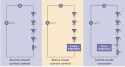
There are generally three different methods of delivering constant current in such a topology with some variations in each of the three cases. Developers can convert the constant-voltage input to a constant current either by a switch-mode topology or alternatively by a linear circuit, and in the simplest case an implementation using a simple resistor to control the current (Fig. 1). Conventional wisdom tells us that a switch-mode converter has the highest efficiency. However, linear approaches offer similar efficiencies for several applications.
Comparing converters
Comparing a switch-mode buck and a linear converter, the most obvious difference is the considerably reduced number of components for the linear driver. The resistor-based solution is even simpler, but simplicity comes at a price as we will discuss.
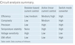
The table affords us a snapshot of the qualitative performance characteristics of our three options. As you can see, the switch-mode approach offers a performance advantage across the attributes considered. You can see that performance indicator values deteriorate from the switch-mode converter to the active linear converter and even more for the resistor-based solution.
A development team faces a decision when looking at the three options as to whether the performance fits the application at hand and how factors such as cost and size come into play. Some typical applications where linear current-controlled LED drivers find success are backlit signage, channel letters, LED strips, automotive interior lights, emergency lights, or multi-channel/color applications for decorative and architectural lighting. Other use cases are in lighting for home furniture, home appliances, and retail equipment like refrigerators, freezers, and vending machines.
Where linear wins
Common to all these use cases is the very limited space availability. Resistor-based or active linear control help to meet this requirement as only a few, very small components are necessary. From a cost impact and design complexity point of view, the resistor approach is the more favorable. Resistors are often found on seasonal products like Christmas lights and decorative residential lighting. But for applications that are more robust and demand higher reliability and quality, the linear control solution holds several advantages:
- Homogeneous light output independent from the forward voltage and heating up of the LEDs
- Consistent brightness over long lines despite the voltage drop
- Light intensity is unaffected by supply voltage fluctuations (flicker/ripple suppression)
- Overtemperature protection extends LED lifetime
- Lower margin needs allow higher effective LED currents
- Additional dimming capability
- Easy and inexpensive extensibility of channels
- Linear ICs
Now let’s examine some specific examples of advantages afforded by linear ICs that were captured in the prior bullet points. A major benefit of a linear LED driver IC is the excellent EMC (electromagnetic compatibility) behavior, comparable to the resistor solution. This is due to the analog control loop that operates without any high-frequency switching. The intended dynamics of the control loop can result in a slight difference in efficiency relative to a resistor approach, but the spectral energy difference is essentially negligible.
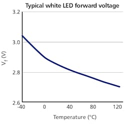
The forward voltage of LEDs depends on several factors. Most prominent are the manufacturing tolerances which can be mitigated by a selection process — binning — based on testing that increases the cost of the LEDs dependent on the accepted tolerances. Another effect that leads to a drift of the LED forward voltage is the ambient temperature. Fig. 2 gives an idea of a typical LED in terms of forward voltage change relative to temperature. For this LED, the Vf change over the whole temperature range is more than 10%. Using a resistor-based design with such an LED would reduce or increase its brightness proportionally over the temperature range. A string of several LEDs in series can compensate or increase this effect. A linear regulator guarantees constant current output within narrow tolerances despite any Vf variations.
Voltage drop and power factor
As mentioned, LED strips are popular applications for linear control of LEDs. Typical LED strips support lengths of 10m (30 ft), and some range even longer. The electrical current needs to travel the whole length and back again. The conductor in a strip has a specific inherent resistance that leads to a voltage drop depending on the length and the resistance of the conductor.
A typical 10m strip with 25 mA required per LED/segment and 10 segments per meter can lead to a voltage drop of approximately 1.5V. With a resistor-based solution, this generates a difference in brightness of almost 10% in a 12V system between the beginning and the end of the strip.
Light fluctuations can also result from the AC-based supply of the DC voltage. For structures with more than 5W power consumption, a lighting system needs to have a power factor correction (PFC) circuit. A cost-effective topology is a single-stage topology that combines the PFC with the generation of the constant voltage. The difficulty comes from the PFC that needs some ripple on the output voltage (5–10%) to function, and only a rather big and costly capacitor can compensate for this requirement.
A linear regulator smooths the current through the LEDs despite the voltage fluctuations due to PFC. This avoids the visible flicker otherwise caused by the current ripple without adding additional components. The same principle confines the visible effects of other voltage perturbations.
Lifetime and temperature
Another factor with all SSL products is that the system design must match or support the long-life benefits inherent in LED sources. The lifetime of LED components correlates with the operating time and operating temperatures. Above a device-specific temperature threshold, the remaining lifetime deteriorates severely. A system design that limits the operating temperature of a luminaire considerably also extends the usability of that luminaire.
There are a number of ways to protect against system operation at temperatures above a specified limit. In the simplest case, you can use a positive temperature coefficient (PTC) resistor, either replacing or supplementing the current limiting resistor. A closer look at the functionality of a PTC thermistor, however, reveals a temperature characteristic that makes the use for this purpose unattractive, as the resistance increases exponentially after a certain threshold temperature. Therefore, this approach does not work for most use cases.
Some linear ICs provide temperature protection with a more seamless transition property. This operational functionality is maintained during low-temperature incidents, providing at least some partial light output. The use of the feature is easy, as it does not require any special effort compared to the calculation, selection, and purchase of the right PTC.
Operating temperature can further impact cost and efficacy of the LED array in a product. With a linear LED driver IC, the current through the LEDs is independent
of the supply voltage as long as it is higher than the sum of the forward voltages of the LEDs and the voltage drop of the IC itself. But with temperature extremes, a potential problem arises.
In a 12V system based on the LED documented in Fig. 2, a linear design would only work above a temperature of approximately -30°C with a low-drop (~ 0.15V) controller and four LEDs in series. With many legacy linear driver ICs, the voltage drop is above 1V. With the rest of the setup being the same, such a legacy IC would work at temperatures higher than 40°C only, which essentially requires a reduction of the string length to three LEDs. A linear IC with low voltage drop provides more design freedom — in this case, four instead of three white LEDs — and leads to improved efficiency.
Dimming and control
Next, let’s consider that most modern illumination systems usually require a dimming capability. For a smart building environment, dimming is mandatory. In resistor-based systems, the only option to enable dimming is by pulsewidth modulation (PWM) of the DC supply voltage. The resulting average current is determined by the duty ratio (on-time/cycle length). This brings additional challenges to the system design as the PWM switch needs to carry the load of the whole chain — in a 10m strip system, such as discussed earlier, this requirement amounts to a 2.5A load.
In order to reduce the total voltage loss below 0.1V in the PWM switch, an expensive switch with a maximum resistance of 40 mΩ is needed. Many applications require stable light output without variations; therefore, the PWM frequency needs to be high enough to avoid flicker (according to the IEEE1789-2015 recommendation, the frequency should be higher than 3.0 kHz). Switching a current of 2.5A at this frequency that flows through a 10m cable back and forth creates problematic radiation.
Many linear LED driver ICs are dimmable in the same way. To avoid the EMC problems, a dedicated signal is guided to every regulator and reduces the transferred charges by 1–2 orders of magnitude, and scales the EMC problem by the same amount.
Smart and connected
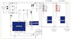
Advanced SSL applications also bring special considerations. The emerging trend of smart lighting or smart buildings requires many additional features that can be realized via a multi-channel architecture. For example, so-called human-centric lighting (HCL) changes the correlated color temperature (CCT) of the emitted light. Typically, such a tunable light source relies on two channels with different CCT LEDs, each channel independently dimmed to achieve a blended CCT. The mixture of the two intensities produces a resulting color temperature between the two extremes. Therefore, the light can be adjusted to the target CCT — for example, 6500K in the morning and 2400K at night. This scheme follows and supports the natural biological rhythm of the human body. The full system design is straightforward and cost-effective as only one AC circuit is required and the electronics dedicated to the different channels are low-cost, small, and of little weight. Fig. 3 shows an example system.
This scheme is expandable to any desired number of channels; thus, it makes the implementation of four-channel color lighting easy and cost-effective. Other applications that use multiple channels such as a chandelier or special-effects illuminations benefit from this simple architecture as well.
Infineon offers a broad LED driver IC portfolio with different operating characteristics. One of the latest members of the BCR linear LED drivers is the BCR431U. This device has an outstanding low minimal voltage drop, lower than 150 mV, providing all of the aforementioned advantages. The extremely low voltage drop enables common 12V systems with four (instead of three) LEDs, or in 24V systems eight (instead of seven) LEDs in series.
Such a design reduces the losses of the whole string by about 25%. The gain allows either reducing the current for the same light output or increasing the light output with the same current. The reduced current has a positive impact on the overall system performance as the reduced current for the same light output will also reduce the resistive losses over the wire by more than 50%. For the given 10m strip example, with the same light output the total energy consumption drops from 30W to 22.5W, meaning a reduction of 25%.
Based on the preceding information, one can easily conclude that the capabilities of linear LED driver ICs promise to advance lighting applications. These advanced capabilities mark the return of the linear LED driver.
Get to know our expert
KURT MARQUARDT is senior director of LED lighting systems and product marketing at Infineon Technologies.

