Manufacturer binning of LEDs can help ensure consistent luminaire performance, but Zumtobel and CD-Adapco engineers explain that optimum designs require thorough characterization of the chosen LED components and system simulation to prove out luminaire designs.
Luminaire makers working with LEDs face the tough task of robust product design time and meeting the accelerating market windows tied to the transition to solid-state lighting (SSL). The development process, however, is complicated by the physics of the LED and how the components react in a specific system design. One way to accelerate the product development and project finished luminaire performance is simulation. Zumtobel has found that coupled thermal-electrical simulations that cover LED performance from power-on to steady state can lead to robust luminaire designs.
LED manufacturers sort their products into bins based on forward voltage, as well as other characteristics, with the purpose of delivering the most consistent light possible. Despite the tight grouping of forward voltages in these bins, manufacturing tolerances continue to lead to significant variations in both current draw and temperatures inside the LEDs, resulting in a range of colors, even within the same batch. These discrepancies also undermine the most noteworthy selling point of the LED — its long operational life. Zumtobel, a supplier of integral lighting products for professional lighting applications, has addressed this problem by investigating the highly interconnected process between the thermal and electrical characteristics of LEDs using coupled simulations with STAR-CCM+ and NGSPICE software.
First, let's consider the issue at hand. LED manufacturers typically document the forward current versus forward voltage (I-V) characteristics of a typical diode. The characteristics are generally presented on a graph of the electrical performance and also graphs that depict color and flux characteristics tied to the electrical operation. That information is insufficient for a developer of SSL products to predict system-level performance.
When placing a forward voltage across an LED, as is the case with any diode, the current initially doesn't flow until the forward voltage is increased to a level sufficiently high to pass a certain threshold sometimes called the compliance voltage. Once the input forward voltage is sufficiently high, current flows freely in the normal conducting direction.
For LEDs, the I-V characteristics at which point current passes and the LED generates photons affect the color and intensity of the light emitted. In other words, although the principal behavior is the same for all LEDs, the light produced highly depends on the current-voltage characteristics of each individual LED.
LED thermo-electrical challenge
Although the working principle of a diode is rather simple, in reality, designing luminaires that produce consistent light, both in intensity and color, can be particularly challenging due to a number of unique operational characteristics of LEDs.
Inherent manufacturing variations in both materials and processes often cause unexpected variations in the electrical response of an LED. As discussed previously, the LED optical output — both total flux and spectrum — is highly dependent on the voltage and current driving it; thus these manufacturing variations can lead to a deterioration of light quality. LED manufacturers attempt to provide a way for lighting manufacturers to avoid inconsistency in end products by binning LEDs based on flux output, color, and forward voltage. And binning does narrow these variations, but it does not eliminate them.
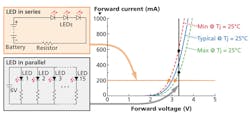
The choice of driver circuit topology — whether the LEDs are electrically in series or parallel — also makes a significant difference in its sensitivity to variations (Fig. 1). To make sure that failure of one LED doesn't cause an entire circuit to break down, they are often placed in parallel on the circuit driver. This means that each light in the circuit operates at the same voltage as opposed to when they are placed in series where the same current flows through each LED. The LEDs in parallel are typically run on the steep part of their characteristic curve, resulting in a higher sensitivity in response to variations in manufacturing within even a single bin, as is depicted in the variation on the vertical axis in Fig. 1.
Much like a computer chip, an LED is also very sensitive to temperature changes. The operating temperature not only affects LED lifetime but determines the optical light output impacting how the eye perceives the LED, as well as thermal characteristics or amount of heat dissipated in the LED-based luminaire.
Problems such as color shift or change in color over time, and luminous flux depreciation or loss in light output over time resulting from temperature variations can quickly become daunting for a manufacturer. One of the main selling points of LEDs is that they can run for 8 hours a day for 15 to 30 years, but if the thermal design is not right, this full potential will never be reached. Indeed, many early SSL products carried such promises and sorely disappointed early adopters, retarding the adoption of LEDs.
Some of the variations described above can be mitigated with electrical control or driver circuitry. The proper design of an LED-powered luminaire that produces both consistent light color and intensity, however, calls for a coupled electrical and thermal approach that can address the interdependencies between the electrical circuit response, temperature, heat dissipation, and cooling approach.
Coupling thermal and electrical
Zumtobel has coupled STAR-CCM+ (a computational software application for simulating flow/thermal behavior) to NGSPICE (an open-source circuit simulation software application) to enable the accurate prediction of the interplaying effects between electrical and thermal behaviors of LEDs. Communication between the two software applications is established using an interactive JAVA macro.
Let's further discuss the approach taken to solve this closely coupled electro-thermal problem. When NGSPICE is executed from the macro, a modeled LED circuit is solved including the forward voltage and forward current of the LEDs. From this data, using a proprietary method developed by Zumtobel, the electrical power is determined. Then using the temperature supplied by STAR-CCM+, the optical power or how much of the input energy that goes out as visible light is computed.
The heat rate that represents the portion of the power that is dissipated as heat can subsequently be calculated by subtracting the radiant power from the electrical power. This heat rate is then fed to STAR-CCM+ which in turn computes all the system temperatures to be passed back to NGSPICE for the next step in the simulation. As discussed earlier, the temperatures have a significant impact on the electrical characteristics of the LED; thus this cycle is repeated until the simulation converges to an equilibrium state.
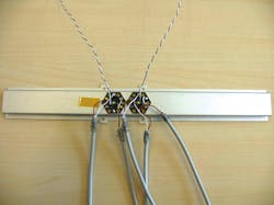
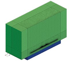
This process was demonstrated and validated on a test luminaire consisting of two LEDs connected electrically in parallel, mounted on an aluminum channel and placed on a wood lab bench (Fig. 2). This model has been extensively validated in the laboratory as it is one of Zumtobel's standard experimental test configurations. A four-terminal sensing method is used to measure current and voltage of each LED. The temperature was obtained through type-T thermocouples placed on specific points of the copper solder pad, printed circuit boards (PCBs), and heat sinks. The thermally-monitored locations were used as reference points for the thermal simulations.
In addition, a parametric study was performed during testing to better understand the impact of manufacturing tolerances (e.g., thickness of the traces, thermal conductivity) on the thermal behavior of the system. One significant detail of the setup that must also be noted is that there is a current meter connected in series with one of the LEDs, which increases the resistance in that branch of the circuit. As a result, each of the lights in the circuit is expected to have a unique electrical response and operating temperature.
Component properties and models
For the simulation, geometrical and material properties of the LEDs were provided by the LED manufacturer and we use half symmetry to keep the simulation time to a minimum. To include the effects of the current meter from the experiment in the simulation, a current-limiting resistor was modeled in series with one of the LEDs in the circuit.
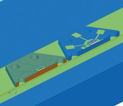
As shown in Fig. 3, significant attention was paid to modeling the important details of the system, including the metal-core printed circuit board (MCPCB) with copper traces, the LED pad with electrical connections, and all the way down to the semiconductor die. For the simulation in STAR-CCM+, accurate capturing of the physics, including natural convection cooling and limiting temperature of the semiconductor die, was key.
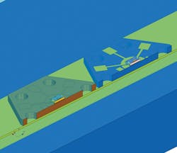
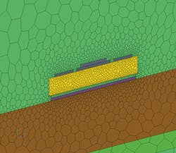
Furthermore, unique meshing capabilities available in STAR-CCM+ were applied to ensure accuracy of the simulations. As shown in Fig. 4, an all-conformal polyhedral mesh was generated and extrusions were used to allow for efficiently using the mesh to model the surrounding air while at the same time capturing the small physical features in the core area of the LEDs themselves. The flow and thermal behavior of the system was obtained by performing steady-state simulations using the segregated flow and energy solvers.
Simulation and results
Fig. 5 shows a screenshot of the coupled interface that facilitates real-time tracking of the various system parameters, including the forward current through each LED and the die temperatures as the simulation unfolds. At startup, an initialization (first guess) of current, temperature, and optical power was made corresponding to initial conditions when the input voltage crossed the compliance voltage. The simulation then continued in time until the LEDs reached a steady state.
During the simulation, for every one step of NGSPICE, ten steps of STAR-CCM+ were performed. After approximately 200 iterations of STAR-CCM+ (which required only about 20 minutes of simulation time on a laptop), the forward current started to converge and the die temperatures settled. A fully converged solution was obtained after approximately 50 updates between NGSPICE and STAR-CCM+.
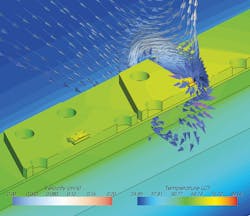
Fig. 6 depicts the surface temperatures of the solids of the system. As discussed previously, the simulation shows exactly what is expected — the increased resistance due to the presence of a current meter (modeled with the current-limiting resistor) in the experiment results in a significant difference in the final temperatures of each of the LEDs. A cut through one of the LEDs also shows the velocity field at convergence, displaying the expected natural convective airflow that cools the system.
Applying the simulation results
LEDs have gained a tremendous amount of popularity in recent years due to their small size, efficiency, and long life. In order to meet high expectations, however, the interdependencies between the electrical circuit response, temperature, heat dissipation, and cooling must be taken into account during the design phase of LED-based luminaires.
To develop luminaires and meet tight market windows, luminaire companies need a way to understand and project finished luminaire performance. For companies like Zumtobel, delivering consistent light with the right intensity and color is crucial to the success of their product portfolio. Zumtobel performs electro-thermal simulations early in the development process and applies that data and knowledge to facilitate the prediction of the performance of a finished luminaire in lieu of physical prototyping and testing. The result can be both meeting time-to-market goals and delivering high-performing products.
PIER ANGELO FAVAROLO is head of thermal management/CFD and LUKAS OSL is an engineer at Zumtobel Group. SABINE GOODWIN is a senior engineer in technical marketing, and RUBEN BONS is the director of electronics at CD-Adapco.
