DAVID DREYFUSS and DON WILLIAMS show how exploiting resonance can be a powerful way to provide distributed passive control of power in individual elements within large arrays. The approach may revolutionize how LEDs are driven and enable systems that have 10 times the reliability for half the cost.
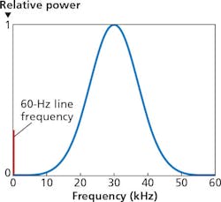
Engineers know well that there can be a critical relationship between power and frequency in both mechanical and electrical systems operating at or near a resonance (Fig. 1). Sometimes resonance is bad and can destroy a system when too much energy goes into a single mode (as in the Tacoma Narrows Bridge disaster). But resonance can also be good and useful. Resonance is commonly used to regulate frequency (e.g., mechanical and electrical clocks) by maintaining just enough power to keep a system oscillating at a resonant frequency. Less familiar, perhaps, is the fact that resonance can be used to regulate power instead. And resonance turns out to be particularly powerful for regulation of power into variable size arrays of variable loads. One example is applying the concept to arrays of lighting elements such as LEDs to realize cost and reliability benefits in solid-state lighting (SSL) systems.
The LED application is particularly interesting, both because of the increasing economic significance of LEDs in lighting applications, and because of the costs and reliability issues that exist with conventional DC drivers in common use. LEDs are inherently low-voltage DC devices with a very steep I-V curve at useful operating points. While it is possible to use a constant voltage source to drive an LED, as a practical matter most designers adopt a constant-current DC driver design as being much more satisfactory. To enable operation at voltages closer to typical power distribution levels (such as 120/240 VAC), luminaires are often configured with many LEDs in series strings. These LEDs have to be closely matched since the light output of each LED is proportional to the common current flowing through the series string. A failure of a single LED (e.g., short, junction failure, or wire bond failure) may result in a failure of the entire string.
AC drive
Various people have recognized that one can also drive LEDs directly from an AC power supply. After all, LEDs are diodes, and diodes are a critical component in any AC-DC power conversion. Furthermore, pairs of LEDs can be connected anode-to-cathode such that one element of the pair conducts and emits light for part of each half-cycle of an AC voltage waveform. Such pairs of LEDs are approximately pure resistive loads. But, in most implementations (e.g., those of Seoul Semiconductor and LynkLabs) such pairs, or more complex network topologies, are still effectively driven by a voltage or current source that is difficult to control precisely.
Interested in more articles & announcements on drivers & electronics?
These AC LEDs are typically designed to run directly on line-frequency power sources. Some embodiments use sufficient LEDs in series to operate directly at line voltages; others use transformers to adapt the voltage to the forward voltage of a single LED or a short series string of LEDs. Most individual LEDs for general-purpose lighting are phosphor-converted blue or violet LEDs based on gallium nitride (GaN) LED technology and have a useful operating voltage range of a few tenths of a volt in the 3-3.5V range.
While AC LEDs are available commercially, they have generally proven to have their own disadvantages that have limited their market penetration to date. They share some characteristics with DC-driven LEDs: the need for well-matched device parameters within a series string and sensitivity to single device failure, for example. They also generally operate at an effective duty cycle (net light emission averaged over one cycle of the AC drive waveform) that can be much less than 0.5, requiring a corresponding increase in device count for a given luminous output. Line frequency drive can also result in significant flicker.
Distributed reactive elements
Using resonance to control power in an array of LEDs overcomes these shortcomings of AC LED drives. In its simplest form, resonance can be used to control power in a single load. Verdi Semiconductor effectively uses resonance in this way to make low-component count, high-efficiency-current drivers suitable for LED strings.
But an even more powerful approach is to distribute reactive elements throughout an array. In this way, not only can overall power to a network of lighting elements be controlled, but within a larger network, subnetworks can also be individually regulated without any active components - meaning without any additional semiconductor devices. Distributed reactive elements enable powerful new control capabilities at high efficiency and low cost. In general, the reactive elements can be either capacitors or inductors. At kilohertz to megahertz frequencies (or even gigahertz frequencies, if desired), the appropriate components are very small and inexpensive, and can be implemented either as discrete devices or on-chip components. For concreteness, we will assume that capacitors are distributed throughout the network, and a smaller number of discrete inductors are used, but it is also possible to fabricate low-cost inductor-based designs as well.
Adding series and parallel reactive elements (capacitors and/or inductors) can open up a whole new approach to power control. Reactive elements can define a resonant tank circuit where the dominant dissipative mechanism is the resistive load of the LEDs. Meanwhile, near-lossless reactances can substitute for the energy-dissipating resistors often used as current regulators in the simplest DC LED drive circuits.
Cells and arrays
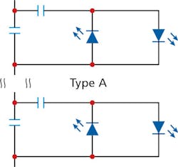
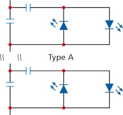
It is useful to think of a network as being composed of a set of cells, where each cell has one or more lighting elements, such as a pair of anode-to-cathode-connected LEDs, plus series and parallel capacitance. Many variations in topology are possible, but one basic cell design is illustrated in Fig. 2. Any number of such cells, and indeed cells of mixed topology, can be connected in series and/or in parallel to form a resonant network comprised of reactive strings. More generally, we refer to a network of reactive strings as “Reactive Strings of Solid-state Lights” (RSSL).
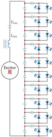
For example purposes, consider a tank circuit including a string of 10 cells as illustrated in Fig. 3. Assume that all LEDs are of the same type, and that all capacitors have the same value C. Each cell has a total capacitance of 2C. The total capacitance of the string is C/5. The resonant frequency of the tank is = √(5LC). The reactance of a cell is = 1/2ωC. As long as X»R, where R is the real resistance of the LED, then the string behaves as if it is purely reactive. This is equivalent to requiring that the tank circuit be underdamped with Q»1.
Detailed analysis of a particular resonant network can benefit from the use of a circuit simulator, but back-of-the-envelope estimates can also easily be made to roughly select component values. For a given operating frequency, the relationship between inductance and capacitance is determined. The capacitance should be selected so that the reactance is big enough to ensure a sufficiently high-Q resonance. The current through each cell is divided between the LEDs and the parallel bypass capacitor and is limited by the series capacitor in much the same way as resistors can be used to control current through LEDs in a DC circuit. Simply use Ohm’s law with reactances instead of resistances to find the desired value. Note that the bypass capacitor serves to store recirculating current locally when it is not flowing through an LED. There is, in effect, local resonant control of the current through each LED in addition to resonant control of current through the string as a whole.
Failure insensitivity
Other properties of reactive strings can be inferred from similar back-of-the-envelope analyses. For example, it should be apparent that current regulation is largely unaffected by both short-circuit and open-circuit failures of individual LEDs. A short circuit prevents current flow through the other member of an LED pair, but other cells are unaffected. An open circuit has the minor effect of disconnecting the series capacitor from the circuit during one half cycle. The actual design tolerance for LED failures can be adjusted by designing for a particular “current utility ratio” - the fraction of the total AC current flowing through the LEDs. Typical practical designs can tolerate up to about 50% LED failure while keeping the remaining LED pairs regulated to within less than 10% of the starting levels.
Dimming can be implemented in a variety of ways. Bulb-replacement products with the driver built into the bulb can be dimmed using legacy phase-control dimmers. For new installations, a better approach to dimming is to intentionally detune the resonance. The detuning can be achieved globally by changing the drive frequency away from resonance. Individual strings within a network driven from a single power supply can be separately dimmed by using a variable inductor such as a magnetic amplifier to detune the local resonant frequency.
Multiple channels and line frequency rejection
While it is certainly possible to operate an entire RSSL system at a single frequency with all the same capacitance values, it is not necessary to do so. In fact, one can view a 2-wire lighting bus as supporting a frequency spectrum with very many available channels. Since any one reactive string only responds within a frequency band, multiple separate bands can operate on the same wiring as long as they operate with sufficient space between bands. Each center frequency can further be modulated and used as a communications channel for data to and from sensors and controls.
As long as line frequency is well separated from any resonant frequencies used for reactive strings, there is negligible response to line frequency and no possibility of line-frequency flicker even without explicit line-frequency filtering. Therefore, no electrolytic filter capacitors are required in the driver.
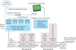
RSSL systems are inherently both electromagnetically quiet and tolerant of noise spikes. Any energy outside of a narrow passband is quickly damped out. Cells and strings of cells can be hot-plugged and unplugged or switched with no effect on the rest of the network. This property can be exploited to share a single higher-power driver among many luminaires. For example, a residence or commercial space can use a single driver located in a distribution panel with a single 2-wire bus supplying power to many luminaires, having LEDs and capacitors but no active semiconductor components, which can be dimmed and switched separately (see Fig. 4).
Touch-safe wiring
RSSL systems are also very human friendly. Typical drive frequencies and voltages are completely touch safe. Live powered systems can be worked on with no danger to the system or to the worker. This can be especially convenient for service and factory rework. Any electrical disturbance just tends to set a resonant string into oscillation, like hitting a piano string with a hammer. For example, if you touch a grounded soldering iron to an unpowered resonant string, it will visibly flicker briefly.
The concept further offers insensitivity to variable forward voltage (Vfrwd) in LEDs. AC drive uses LEDs over their full I-V curve up to some maximum current. As such, one might expect turn-on to be an issue especially in the presence of a distribution of Vfrwd values within a series string of cells, and especially for longer strings. But consider again the example string of Fig. 3. In any cell where the instantaneous voltage is less than Vfrwd, the LEDs do not conduct, the series capacitor is turned off, and the reactance is 1/ωC . As soon as an LED starts to conduct, the reactance goes to 1/2ωC .
The voltage division in the string immediately redistributes to increase the voltage across any cells that haven’t turned on yet. This results in a cascade effect such that once one cell turns on, the rest follow almost immediately, even if they have different Vfrwd values. This effect largely eliminates the need for binning for forward voltage. Furthermore, one need not even use a single type of LED in a particular reactive string. One can freely mix and match according to the needs of a particular application. If different LEDs require different currents, then a different series capacitor is selected to match the LED. One can even freely mix (In)GaN-type LEDs and Ga(Al)(In)(P)As-type LEDs with their very different I-V curves and different Vfrwd values.
Autobiasing to turn on
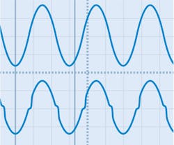
LEDs in reactive strings do not tend to stay in their off-state. In fact, the current waveform through, and therefore the luminous output from, an LED pair is near-sinusoidal (Fig. 5). The LEDs want to turn on, and the voltage waveform moves rapidly through the region between 0V and ±Vfrwd. However, even given that each LED provides light output only over a half-sinusoid, it puts out an average of about 1/3 of the light that the same LED would put out if driven at a DC current equal to the peak AC current.
The average light output may appear to a casual observer as a serious disadvantage of any AC-drive scheme for powering LED lighting, especially given the perceived high cost of LEDs in general and the higher-power devices typically used for lighting applications in particular. However, the disadvantage is not real. First, the upper limit on current rating for any device is typically based on an assumption of DC drive at a particular ambient temperature and with a particular specified cooling protocol including heat sink and possibly additional active cooling.
If average heat dissipation is the limiting factor on drive current, then clearly the specification should be on a maximum average current, and not on a maximum peak current. Unfortunately, to date, no device manufacturer or third party has published any real test data on device failure or lifetime when driven at such higher peak currents using AC drives. (See our feature on p. 55 for information on emerging test standards for AC LEDs.)
One can take the conservative position, instead, of recommending a zero-to-peak current amplitude for AC drive equal to the rated maximum (or recommended) DC drive current. Taking this approach, one needs more LEDs to get the same luminous output as for DC drive. But LEDs themselves, purchased in bulk as dice, are actually cheap and getting rapidly cheaper! In many applications, the raw cost of the LEDs themselves is no longer the dominant cost component in a fully packaged product. Many DC luminaire manufacturers are already using a similar strategy to increase lifetime by under-driving a larger population of LEDs. RSSL systems can be further configured with modular low-cost replacement parts to minimize maintenance costs when they finally arise.
RSSL reliability improves with array size
Using more LEDs would typically be considered a serious reliability and lifetime issue for DC drive, especially given the sensitivity to single component (or connection) and driver failure. This is another issue for which RSSL systems shine. A failure analysis of RSSL systems shows that their overall reliability and lifetime actually improves with array size due to the fact that regulation of remaining components can remain acceptable even with 50% component failure.
Still further, most high-power LEDs show significant luminous output droop at the upper ends of their rated currents, resulting in some loss in net electrical watts to radiant watts conversion efficiency. An RSSL system can be cost-effectively designed to operate such devices well below their rated maximums where the droop is insignificant.
Additionally, cost savings and reliability gains can be achieved in COB (chip-on-board) architectures including multijunction dice. Rather than building a few large-area devices on one chip, one can select a device area, power level, and cooling strategy for maximum single-device efficiency, and then just put as many of these devices as desired on one chip to achieve the desired performance specifications. Drive the array as one or more resonant strings, and you have a product family that can be scaled arbitrarily to any desired luminous output.
Using resonance to control power in reactive strings of LEDs is a powerful new approach to driving LEDs for any array application including lighting. This article has just touched the surface of the characteristics and advantages of RSSL systems. Resonant drive provides a rich and powerful array of innovative design tools that can be further exploited to build sophisticated low-cost multifunction lighting systems. In the future, we will explore additional capabilities that can easily be built onto RSSL lighting platforms including sensors and controls, hue control, Internet of Things (IoT) functionality, system communications, reactive strings as sensors, and free-space optical communications, for example.
RSSL technology is protected by issued and pending patents in multiple countries. Contact the authors ([email protected]) for partnering and licensing opportunities.
DAVID DREYFUSSis scientific advisor andDON WILLIAMSis a director at Intervention Technology Pty, Ltd. (Victoria, NSW, Australia).
