This article was published in the July/August 2011 issue of LEDs Magazine.
View the Table of Contents and download the PDF file of the complete July/August 2011 issue.
+++++
The long-awaited hockey-stick expansion of the LED-based lighting marketplace is beginning to take shape as more replacement fixtures are entering the consumer and industrial landscape. The market potential is leading more product-development teams to attempt their own solid-state-lighting (SSL) designs, whether the product is a small MR16 or a larger PAR lamp. Yet herein lies the issue. LEDs are powerful semiconductor devices, and so allow product developers to deliver a whole new world of differentiation with their designs, such as intelligent lights with sensors and dimming capabilities. Lamp and luminaire designers are no longer defining LED fixtures only in terms of basic lux and color requirements.
In this still-maturing technology segment, many product designers are still coming up to speed on the language necessary to understand how to build any of this potential intelligence into their lighting system. This puts them at a disadvantage when it comes to discussions with potential vendors and partners. The developers, trying to grasp a changing and maturing technology landscape, need an understanding of the basics – the building blocks of intelligent lighting design.
These essential questions can help a developer understand not only how to correctly define a project, but also how to choose appropriate partners, design-service providers and vendors.
Building Block #1:
Do you require dimming?
The dimming question is tougher than it appears at face value. A “yes” answer sets off a daisy chain of follow-up questions including three major issues: input voltage, the dimming scheme, and dimming quality/performance.
Let’s first consider the input voltage. Low-voltage fixtures such as MR16 lamps that have inputs of 12 VAC or 24 VAC make it more difficult to develop a driver that can operate with the majority of the TRIAC dimmers installed in the existing infrastructure. Companies such as Cypress and Zetex are creating such drivers at this time. For standard line-voltage applications, there are many more available drivers that support TRIAC dimming. At the high end, there are a small number of 277V dimmers that are available for high-bay lighting, although the requirement for this feature is trending upward.
The second issue is the type of dimming-control required (see page 49 for more information on dimming-control scenarios). TRIACs were not designed to interface with LED systems but are broadly installed. Your new favorite dimmable AC/DC LED driver may only work with half the TRIAC dimmers installed in typical application scenarios. A driver also may be unable to correctly read the low and high end of the TRIAC and so will only offer about a 20-40% dimming range without introducing flicker, especially on the low-voltage side of the range.
If the dimming control comes from a microcontroller, the power from the AC line needs to be appropriately managed. Standard AC/DC drivers from companies such as Advanced Transformer are not made to power a microcontroller that has a 5V input rail. The microcontroller will also require an input signal to control the modification of the output dimming waveform, which can even introduce the complexity of supporting a communication network to carry the dimming information.
The final issue is the quality of the dimming waveform itself, because all dimming circuits are not equal. Dimming is nominally done via a pulse-width modulation (PWM) signal, a digital waveform used to control power (usually current) to the load based on the PWM duty cycle (from 0-100%). But the PWM signal can introduce complications via EMI noise that can result in LED flicker and create obstacles in the regulatory approval process.
The details of PWM signal control are beyond our scope here, but product designers should look for low-noise implementations. Some drivers use pseudo-random control of the PWM signal to greatly reduce noise.
Dimming performance can also suffer in terms of how smoothly a light dims if the control comes from a digital output. An 8-bit PWM waveform only has 256 possible steps that can dim a string of white LEDs. Especially at the low-end of the dimming range, those individual step changes become visible to the user. However, a 16-bit PWM has over 65,000 steps, allowing for a much smoother dimming curve.
Building Block #2:
Do you require feedback?
The notion of actually being able to adjust the operation of a light engine on the fly, based on input from sensors and operating characteristics such as temperature, is an advantage that LEDs afford. Yet the concept is new both to product developers working on lighting and to lighting designers.
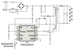
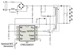
In the case of LED lighting, sensing and control can yield more robust products from a lifetime standpoint. In part this is due to proactively preventing potentially-damaging operating conditions. Any LED system should be able to appropriately track different conditions such as overvoltage, undervoltage, short circuit, open circuit, and thermal runaway. Let’s consider how monitoring these conditions can be leveraged using Fig. 1. While this is an example using a Cypress Semiconductor driver, other IC vendors support similar sensing in simple white-light applications.
The circuit also includes a temperature sensor and will shut down if the temperature rises above a set threshold. Temperature is the bane of the existence of LED lighting design engineers, since LEDs conduct all their heat through the base. This puts the engineers into an uncomfortable position of having to work as much on thermal design as on electrical design. This ensures that temperatures do not rise beyond datasheet junction temperatures of the components on the PCB board and cause a failure. Also, it’s widely known that temperature dramatically affects the flux and color output of the LEDs themselves, which can make the visual appearance of a row of fixtures appear to be different in color or brightness.
A system with added intelligence and driven by a microcontroller can implement an improved temperature-compensation algorithm using a simple and cheap thermistor placed near the LEDs themselves. After reading the board temperature, a well-known equation is used to calculate the junction temperature of the LEDs. Junction temperature is equal to the temperature measured on the board plus the product of the thermal resistance of the board, the constant current of the LEDs, and the forward voltage of the LEDs. These are all easily-discoverable values. The calculated temperature can then be used to derive any adjustments to the drive current or voltage in order to keep the flux output (or the color output of an RGB series of LEDs) inside the visible limit.
Building Block #3:
How do you want to drive the LEDs?
This is another simple question that becomes more complex the moment you bring a power engineer to the table. When faced with the omnipresent cost question, most engineers will quickly turn to a linear implementation, which can cost half of the switching alternative. Unfortunately, the tradeoff for using a linear drive system is about a 50% hit in the overall system efficiency, and that tends to counteract the green energy-efficiency advantage of LED lighting.
Switching implementations typically use either a step-down buck or step-up boost topology. There is a wide range of suitable driver ICs on the market that support such topologies. But product developers should keep a critical eye on a few operational features that can crucially impact performance.
The first is switching frequency. For example, if a driver is able to switch at 1.5 MHz rather than 1.0 MHz it will reduce the size of the inductor needed for the circuit, which in turn helps solve the inevitable board-space crunch in most retrofit applications.
A second key specification is a resistance value called RDSon, which is associated with the high-voltage MOSFET that switches the output and in some cases is integrated in the driver IC. If that RDSon value is too high, over 1 ohm for example, then the power dissipation will suffer, again killing the efficiency of the system. The final key concern is the driver efficiency specification. A decent switching regulator can get up to 95% efficiency, which can differentiate a lighting system effectively in this competitive marketplace.
Building Block #4:
What’s going to set your product apart from the competition?
To be frank, this final question is about the sum of the parts of a lighting-system design that truly differentiate a product – or the lack of differentiating features. There is a veritable crush of companies seeking to carve out a space in this burgeoning LED retrofit market. Many will simply decide to create a non-dimmable or TRIAC-dimmable LED fixture or lamp and try to win in the market based on low cost. These companies will rise and fall based on the commodity pricing of basic components, not on the quality of their overall system.
Companies who instead desire to push forward with a combination of simple differentiating techniques will carve out unique and stand-alone spaces for themselves. Many lighting engineers simply don’t know enough of what’s available in the semiconductor market to take advantage of simple solutions. These techniques include some features in LED retrofit bulbs and fixtures, and other features in complete lighting system designs. Fig. 2 depicts some examples.
Consider as a second example a table lamp. In the simplest fashion it takes an offline signal and drives a set of white LEDs with no dimming. Again, there are multiple vendors in the market designing this lamp. However, the development team can differentiate the product with the addition of a capacitive touch-sensitive slider on the lamp to both turn the light on and off and to adjust the dimming level. Adding a capacitive slider to a design that already includes a microcontroller can cost as little as a line of copper on a circuit board. In other words, it is not expensive but yet again provides a unique advantage.
As a final example, consider outdoor backlights, such as those used behind restaurant signs. To save energy, the restaurant will want to drive the sign at different levels in the day or at night. But the simplest version of an SSL design will not allow such control.
There are driver ICs that allow software control of the constant current used to drive the LEDs. For example, the level might be software-adjustable from 350 mA to 700 mA – significantly changing the brightness. Such an LED backlight design can offer even more energy savings to the potential customer, maximizing efficiency during the entire day.
There are far more examples of features the lighting-product developer will encounter as LED technology continues to mature. Examples include additional communication interfaces, control mechanisms or thermal platforms. Differentiating a product in this market is not an onerous process, does not have to be costly, and can ultimately help a company position itself effectively. The building blocks discussed here are obviously not the only questions necessary to create an intelligent lighting fixture, but they offer an excellent starting point to successful products.


