This article has an appendix containing further details and software routines - download the appendix.
+++++
When a set of LEDs is controlled for a lighting application, LED luminous output versus electrical power is a key specification in determining the quality of visible light. In low-power applications, illuminating an entire set of LEDs simultaneously to achieve the maximum luminous level may not be possible, due to limitations in current source. The control electronics must efficiently manage the power dissipation per LED to produce optimum luminous output from the low-power source. This requires a power-management technique where, in a set of LEDs, only one bank of LEDs is powered for a given time. The design must manage this time interval to achieve the required luminous intensity.
The drive circuit discussed here depends on the fact that the human visual system will discern constant light when an LED is switched on and off above a certain frequency. Generally, a system that lights the LEDs at least 60 times per second (60 Hz) will not exhibit flicker.
In order to determine the number of LEDs in a system, and the number in a bank that must be lit for each given time interval, the circuit designer must first consider the available power and the luminous intensity required for the application. The circuit designer must carefully review the LED datasheet for luminous intensity versus forward-current characteristics, to select LEDs that meet the required intensity level. Once the number of LEDs needed to achieve the required level of luminous output from the application is determined, then the number of LEDs that can be powered at a given time interval is determined by taking the ratio of the total current required for the LEDs and available current, as follows:
Number of LEDs in a bank = total required current for LEDs / total available source current
As discussed above, the circuit designer must consider the frequency at which the bank of LEDs is turned on and off and the specific on- and off-time characteristics. The on time must, at a minimum, be long enough for full illumination of a bank. The off time is limited by the time it takes before the bank of LEDs start to visibly dim. Essentially, the off time limits the number of banks that can be controlled via time-interval management because excessive off times would create flicker.
Flip-flop-based driver
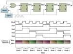
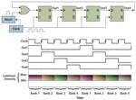
A low-cost implementation of this technique requires a clock source, digital flip-flops to control banks of LEDs, and an OR gate to detect a start condition with a simple on/off switch. Fig. 1 shows a block diagram of a D flip-flop configuration that can control four banks of LEDs.
The limitation of this implementation is that it is monotonic, and does not provide design flexibility. It only has an on or off state. For some applications, such as LCD backlights, this circuit may be adequate. However, if dimming or pattern generation is needed, a microcontroller (MCU)-based circuit provides the greatest flexibility with minimum impact to the total cost of the solution. The circuit is also simpler to build, with fewer components. The MCU controls each bank of LEDs, and it can also detect user inputs for dimming control and pattern selection.
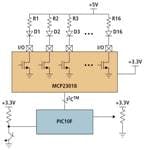
One example of a cost-effective implementation is to use a low-cost and low-pin-count, 8-bit MCU, such as Microchip’s PIC10F or PIC12F family, with an I/O-port expander such as Microchip’s MCP23018. I/O expanders can also be useful for driving LEDs, when the lighting circuit is remotely located with respect to the MCU.
MCU and I/O expansion
I/O-port expanders are devices that are used to expand the number of I/O signals to which an MCU has access. In this application, the MCU controls the I/O-expander ports via the I2C protocol, to drive the LEDs on or off. And the MCU’s integrated I/O pins can be used to detect user inputs via a push-button switch, or by utilizing the built-in A/D converter (analog-to-digital converter) to detect a potentiometer level for dimming control.
In this case, when the I/O port is set as a logical low or zero, then the voltage at the I/O-expander port is 0V and current flows, which forward biases and turns on the LED. The LED-biasing resistor, which also functions as a pull-up resistor for the open-drain output, limits the current to the LED for the required luminous intensity.
When the I/O-expander output port is set as logical high or 1, the open-drain output is off or high impedance and the voltage at the I/O-expander port is pulled up to 5V by the pull-up resistor. This is an off state for the LED, because current will not flow.
The open-drain-output configuration offers another advantage when the port is configured as high impedance or in the LED off state. The LED does not turn off immediately due to parasitic capacitance. Therefore the effective on time for each bank is extended for a slightly longer duration than the circuit-design calculations would indicate because the next bank of LEDs will turn on prior to the former bank extinguishing. You don’t realize that benefit with a push-pull output.
Sharing current
The MCP23018’s 16 I/O ports can drive up to 16 LEDs. The I/O expander’s output drive capability also limits the amount of current that can be sunk into the I/O port when the LED is fully turned on. The I/O port’s low-level voltage is specified for 0.6V maximum at 8.5 mA of current. If the current is higher than 8.5 mA, then the low-level voltage will increase slightly although the impact is negligible so long as maximum current is kept to the specified limit of 25 mA.
Let’s consider an example where the total source current is limited to 50 mA at 5V. If you budget approximately 2 mA for the microcontroller, the I/O expander and the resistors for user-input detection, then the rest of the available current can be dedicated for LED lighting. If the luminous intensity of the LEDs at approximately 10 mA is adequate, then 4 LEDs can be controlled per bank. And, the current-limiting resistor value will be approximately 440Ω.
The timing shown in Fig. 1 can be replicated using a relatively short MCU program. The appendix to this article provides details of such an implementation with pseudo C Code that would be used to control the MCU. We will present a simpler description here.
The main segment of the program would consist of an infinite loop. A timer integrated on the MCU generates a periodic interrupt based on the required timing that has been determined in the hardware design stage. Each interrupt would result in the next bank of LEDs being refreshed. With such an implementation, the circuit outputs the required luminous intensity, and to a person it appears that all LEDs are turned on simultaneously from the available power source.
Patterns and dimming
You can easily extend the MCU-based design to add support for light patterns or dimming. The web addendum includes sample code for these concepts as well.
Dimming control requires the addition of pulse width modulation (PWM) to control the duration for the on-time interval of each bank. Fig. 3 shows a timing diagram for such an application. The width of the tPWM_High pulse determines the intensity of the LEDs in each bank. The online example uses a thumb-wheel potentiometer with the center tab connected to the MCU’s A/D-converter input. At one end of the potentiometer range, the LEDs are set to the lowest dim level and by adjusting the potentiometer the brightness can be increased over 16 steps.
You can further extend the concept and methodology described here to generate chasing and other complex patterns where a single, or small group, of on or off LEDs is varied in a dynamic pattern. Such a design might require a more capable MCU such as Microchip’s PIC16F family that has sufficient on-chip memory to handle the program required for sophisticated lighting patterns, such as chasing lights.
While there are many methods to efficiently drive the banks of LEDs used in LCD backlights or lighting-pattern applications, designers are always looking for novel ways to cut costs without compromising performance. In low-power applications, LEDs can be controlled by managing the time interval for each bank of LEDs, for efficient illumination. In addition, low-pin-count MCUs and I/O-port expanders provide a low-cost alternative for lighting solutions with great design flexibility.
