This article was published in the November/December 2013 issue of LEDs Magazine.
Visit the Table of Contents and view the e-zine version in your browser. You can download a PDF of the magazine from within the browser e-zine.
+++++
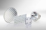
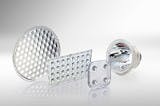
LEDs are quite different from conventional light sources in many ways including in optical behavior where legacy sources primarily emit omnidirectionally and require a reflector to shape the radiation. LED point sources radiate in one hemisphere and often require the use of collimators in the form of total internal reflection (TIR) lenses to steer the beam. But optimum solid-state lighting (SSL) product design requires an understanding of both reflectors and lenses (Fig. 1), and we will describe the physical foundation of these optics and help guide the selection and optic design process.
Due to the typical layered structure of an LED chip and built-in primary optics in the package, the emission of light is approximately Lambertian. Sometimes this basic emission is further influenced by additional optical means that are integrated into the LED, often featuring a reduced beam angle. The challenge for the SSL developer is further control of this pre-formed emission.
Optic control is often implemented with collimator lenses — bulk optics that implement total internal reflection. A second optical concept, also well-known and ubiquitous in conventional systems, is the reflector. Its market share seems to be increasing for good reasons — the power density and size of modern LEDs. This article will present an overview of the properties of different optics and describe the advantages and disadvantages of each, including materials. Special attention will be given to the materials those optics are made of.
Optics options
Optical components can be classified by the physical principles that they rely on. Influencing the propagation of light can be done in different ways. The target of the efforts is the manipulation of the light's properties; in the case this article is dealing with, the main property is the direction of the radiation. In the concept of ray optics the emission of light sources is represented by individual, distinguishable rays. Lenses will refract the light, while reflectors will change the direction of propagation by reflective means.
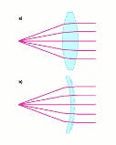
In the case of lenses one can take advantage of the fact that light's behavior depends on optical densities when propagating through materials and reacts in deterministic ways. In a very simple but nevertheless common case one of the media is air with a refractive index of η ≈ 1. For the second medium another material such as PMMA (polymethyl methacrylate) or PC (polycarbonate) can be chosen. Glass can also be used to create extraordinarily good optics. Refractive indices of commonly used glasses are in the range of 1.3–2.2. The borosilicate glass used by Auer Lighting, for example, is called Suprax and features an index of refraction of 1.482 and an Abbe number of 64.5 while showing very good transmission properties in the visible spectrum. Fig. 2a and 2b show ray patterns of some typical lenses.
Reflectors
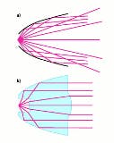
There are several ways to implement a reflective surface starting with highly-reflective metals. Another option is to coat a substrate material accordingly by appropriate means. Also glass is a good choice as a substrate material. Suprax, for example, shows a low coefficient of thermal expansion (4.3 × 10⁻⁶) and it can be coated easily. At Auer Lighting we use a PICVD (plasma impulse chemical-vapor deposition) process to apply customizable coatings in a fast and economical way. With this technique, layers of SiO2 and TiO2 will be deposited from the gaseous phase alternately. By engineering thickness and the number of layers as needed, the coating's spectral characteristics are defined effectively. Reflectors perform optically as shown in Fig. 3a.
Besides lenses and reflectors, there are solutions for optical problems that take advantage of both worlds. Let's call them hybrid optics. A special form of such a hybrid optic is the collimator, which enjoys great popularity for LED applications. Such a device exhibits lens-like features at the first and the last optical surface and reflective properties in between (Fig. 3b).
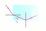
In most cases the reflectiveness is not due to a coating but makes use of the TIR phenomenon. TIR is a consequence from the underlying physical principles. When the light rays hit the surface between media coming from the optically denser side above a certain critical angle (Fig. 4a). Prisms on the outside can support this effect even if the contour of the collimator itself would not allow for this critical condition. In principle, this effect is lossless. So collimators may also be thought of as bulk lenses with reflective properties.
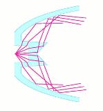
The concept of a reflector with lens features operates in a reverse manner. Here a lens structure is added in the center region of the LED to the reflector in order to gain control over the direct emission from the light source (Fig. 5).
Pros and cons
Lenses and reflectors show significant differences when comparing their advantages and disadvantages in solving specific optical problems. That makes them more or less suitable for different tasks. Let's consider the facts.
Up to now the line between the optics was drawn between lenses and reflectors. However, in LED applications, classical bulk lenses are rarely used. Even the lighter-weight Fresnel lenses are only rarely seen. Instead, the already described collimators are typical and we will concentrate on them for the time being.
In general, simple reflectors are limited to only one interaction between light and surface due to the underlying optical principle. This has direct implications for pros and cons with efficiency being a positive. Since the light doesn't have to enter the substrate material but interacts directly at the surface, coefficients of reflectivity of up to 98% can easily be obtained with sputtered coatings. The very same holds true for the described PICVD method of deploying highly reflective dielectric coatings on substrates such as glass or plastics.
The single interaction between light and matter will also limit the influence of inevitable manufacturing tolerances (contour deviations, surface roughness) and allows for their control or even compensation, respectively. Another important criterion for cost-effective production and quality of the optical element is its size and consequently the amount of material being used for it. For a reflector the glass is only the substrate material for the coating and its thickness can therefore be limited. A direct consequence of this fact is the easy scalability of such a solution to comply with bigger light sources.
As many new LEDs feature a relatively larger LES (light-emitting surface) of late, scalability is an important advantage for glass. Indeed, the trend toward chip-on-board (COB) LEDs makes reflector solutions look even more attractive.
Obstacles for reflectors
Despite all the advantages there are also drawbacks when using reflectors. While being a positive aspect when it comes to tolerances, the one and only interaction between light and surface limits the possibilities to alter the rays' path. That means many optical features have to be implemented in only one surface such as ray deflection via the contour, controlled scattering via facets, and/or spectral filtering via the coating, thus adding complexity.
The downside of the open and lightweight construction of a reflector is its inability to take control over light that is emitted from the LED directly into forward direction. Only the fraction of the light that will be emitted laterally will interact with the surface of the reflector and can be manipulated. This fact is negatively affected by the LEDs' characteristic emission pattern that has a strong bias on forward light. Unpleasant light distribution characteristics are often seen as a consequence of this, leading to unwanted color distribution effects or a background illumination called spill light. The latter effect is especially noticeable with systems of smaller beam angles such as lamps with a full width half maximum (FWHM) angle less than 20°.
One possibility to counteract that behavior is to increase the depth-to-diameter ratio of the reflector, limiting the solid angle of direct emission. As this is not always possible due to physical or manufacturing restrictions, a certain effect remains. The open front of the reflector will also require additional encapsulation when a shielding of the LED to environmental influence is desired.
Collimator advantages
Collimators, on the other hand, have the inherent ability to protect the light source from the surroundings when designed accordingly. Its concept relies on a bulk optical approach trying to capture most (if not all) of the LED's emission and gain control over it. Forming a cavity around the light source assures this and helps with the shielding. So with this approach already two surfaces are ready to take control over the light (the entrance and the exit surface of the collimator) by means of contour, micro-, or Fresnel lenses.
The third place that is optically active is the reflective boundary of the collimator. Most commonly, TIR is used here to ensure highly efficient ray deflection. All the surfaces need to be manufactured very precisely to allow for best performance without unwanted light loss or distribution issues — a potential disadvantage.
Moreover, the light has to enter a medium with higher optical density and has to leave it as well. Both processes exhibit Fresnel losses that can only be suppressed by additional antireflective coatings that are potentially costly due to two separate surfaces that have to be covered. The light will also have to travel relatively long distances within the optical material, giving rise to internal absorption effects that have to be taken into account. Efficiency-wise this is a drawback.
Enabling an optical element like a collimator to efficiently collect all of the emitted light requires its dimensions to be at least as big as the light source. As already mentioned, collimators are bulk optics. This fact together with the increasing size of modern LEDs will result in even bigger optics that will be increasingly hard to handle and will drive costs as well as decrease performance.
Another issue worth mentioning is glare. Since many lens optics are small, high luminance values will occur and lead to discomfort or even the inability to see. Reflectors, on the other hand, can be easily designed large enough to spread out the light flux and hence to lower luminance values to pleasing values.
Present and future
Drawing on experience in actual SSL projects using reflectors and lenses, we can share some observations of the present state of optics design and the future. One major goal of a project was the development of a family of reflectors to be used with a Zhaga-compliant LED light source. This family of reflectors was targeted at 10°, 15°, 25°, and 40° beam angles, respectively. The project sought to use the reflectors for an LED fixture that could replace conventional MR16 lamps.
Boundary conditions specified a common height and diameter for the four optics. Needless to say, a reduction of color effects of the LED was also required. In the end, we came up with proposals that fulfilled all the goals and showed some interesting details about the limitations of reflector optics as mentioned in the paragraphs before.
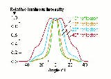
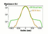
Fig. 6 shows the luminous intensity of the various reflectors relative to beam angle. All the optics showed superior color mixing and superb efficiency. The 40° and 25° reflectors, in particular, show very nice light intensity distributions, beating standard MR16 products easily. Even though the 10° and 15° optics also show a pronounced peak and a nice slope, a slight halo of spill light becomes more visible with smaller beam angles (Fig. 7). This halo effect is caused by the light that is emitted by the LED but never hits the reflector surface and leaves the setup directly.
We observed the same halo effect in another project with a specified 10° beam angle, and we worked to overcome the issue. When it comes to large, higher-power LED modules such as COB LEDs with several dozen single chips beneath a common phosphor layer, TIR optics become less desirable due to the high weight. Although a reflector would be a better choice, the direct light that is always present limits their use for small-angle spot lights.
Hybrid optics
One way around this dilemma is receiving increased attention lately ° taking the previously mentioned hybrid optic a step further. A reflector that serves as the primary optic is modified with a bulk transmission optic at the light entrance hole. The basic idea is to gain influence over the direct light while keeping the weight of the overall optic low. If the design is done properly, the hybrid optic can be manufactured as a single piece, which makes it as easy to use as a reflector or TIR lens.
In contrast to a cover lens that is placed on top of the reflector, this hybrid design influences different parts of the light beam independently. A cover lens will transmit all light, whether it comes from the reflector surface or the LED. Due to the difference in incidence angle on the lens, it is difficult to design a lens with desired properties. A lens at the bottom of a reflector can be shaped such that light usually hitting the reflector will pass it almost uninfluenced while the remaining part, which would miss the reflector in the first place, can be reflected or refracted.
There are two possible ways to design such hybrid optics. The optic can either focus the direct light sufficiently so it does fall into the angular range of the reflected light or it directs the light onto the reflector. Both principles have their advantages and disadvantages. Directly focusing the light becomes increasingly difficult with large LED sources due to the étendue limit. Directing the light onto the reflector requires either quite large optics if the TIR principle is used or an additional coating step. Furthermore, the light must be directed onto the reflector at the proper angle so it is reflected in the same way as the light not going through the bulk optics.
Even though both of these methods present some challenges in the design process the reward is worth the effort. With such a "reflector-lens," a well collimated spot can be realized that has greatly reduced spill light, almost comparable with classic spotlights using incandescent sources.
The spot is not only more pronounced without the direct light halo but also reaches a higher candle power (Fig. 7).
While lenses and reflectors and even their hybrid siblings have their pros and cons, the bigger COB sources will also lead to another important topic ° materials. Up to now it was sufficient to use relatively cheap plastic materials for collimators and metal or plastics as reflector substrates. But the latest improvements in LEDs lead to lumen packages and energy densities that will exceed the specifications, mainly temperature characteristics, of the mentioned materials.
For example, automotive applications have to use highly powerful LEDs to generate enough light flux to be used in headlamp systems. Here, light guides with a length of some centimeters are used. But the slightest variations of the absorption characteristics inside such a light guide that is made of PMMA or PC will lead to a local power accumulation, raising the temperature of the material easily above its melting point.
Glass, on the other hand, can be operated at temperatures up to several hundred degrees centigrade and therefore easily withstand such phenomena. The very same is true for systems that are used for the entertainment industry, where manufacturers try to make use of high-power LEDs.
For a short, naive moment one could expect that LEDs require only cheap, small optics to work since they are so tiny and efficient, and barely generate heat. But LEDs have already become very efficient and bright, and no one doubts they will deliver further increased brightness and efficiency in the future. They have at the same time become bigger and bigger, producing more and more heat. That trend could lead the SSL industry back to reflectors and glass as the best optical choice.
