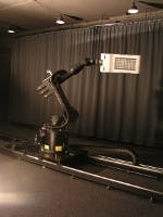
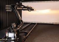
Luminous intensity distribution describes a fundamental characteristic of luminaires including LED-based solid-state lighting (SSL) systems. A goniophotometer is generally used to measure this property. The usual setup comprises a mechanical goniophotometer with a horizontal and vertical axis for rotating the test sample and a photometer for measuring the luminous intensity over a given distance. Nowadays, robots are used for this purpose to extend measurements and enhance measurement accuracy. The German company opsira presented its system called Robogonio at the LED professional Symposium + Expo 2013 in Bregenz, Austria, and explained product details.
Goniophotometers measure the spatial distribution of light visible to the human eye at a specific angular position. The following photometric values can be determined with a goniophotometer:
- Luminous intensity distribution in candela (cd) and illuminance distribution in lux (lx)
- Luminous flux in lumen (lm) by integrating the luminous intensity distribution
- Angle-dependent color coordinates and correlated color temperature in Kelvin (K)
- Retroreflection in millicandela per lux (mcd/lx)
One of the first goniophotometers with three long-armed robots was developed and put into operation five years ago at the German PTB (Physikalisch-Technische Bundesanstalt) in Braunschweig, Germany. Each of the three robots has seven controlled axes for moving the slim arms with a length of more than 6.40m. One robot carries the light source in a freely selectable burning position, aligns it in the instrument center, and holds it in position during the measurement. The other two robots each align a photometer head with the light source and divide the room into hemispheres. They can move on any paths at distances of 1–3m and with typical measurement periods of 10 minutes to 1 hour.
The orientation of the robots in the room as well as their kinematic characterization is determined by means of a laser tracker system. This results in path deviations of the photometer head of <0.6 mm, and on average only 0.2 mm. The movable photometer heads and a monitor-photometer head are each designed as a tri-stimulus colorimeter head with four channels. In addition, they contain an unfiltered silicon (Si) photodiode for radiometric measurements and a charge-coupled device (CCD) array spectrometer. Thus, light, color, and optical radiation are measured through the same light-entry window; all photocurrents are measured in parallel and converted to frequencies. This allows the simultaneous measurement of all 18 channels with synchronous triggering and any integration times whatsoever, optimally adapted to the motion sequences of the robots and the modulations of the light. This huge robot-goniophotometer was used only at the PTB to offer characterization of luminaires as a service.
But now the lighting industry has the possibility to perform these characterizations in-house with opsira's Robogonio robot-goniometer. It enables flexible measurements of a number of angle-dependent photo- and radiometric parameters, combining various advantages of different conventional goniometer types into one device.
The solid six-axis construction of the goniometer supports the positioning of the samples (light sources and luminaires) as well as the manipulation of their angles with high precision and reliability. The high number of mechanical variances allows measurements in the traditional A, B, or C planes by using one single measurement system that combines the goniometer types 1.1, 1.2, and 1.3 according to DIN 5032 (CIE 70-1987) in one device. Depending on the configuration, the goniometer types 2.x, 3, and 4, and particularly type 3.2 are available.
By using a robust industrial robot, the user gains the advantage, of reliability, geometric flexibility, and worldwide secure investment. The Robogonio is able to concretely measure luminous intensity and radiant intensity distributions (EULUMDAT, IES, etc.), color distributions as well as luminance distributions (glare). Near-field goniophotometric measurements to generate ray data, for example, are also possible. Furthermore, with the Robogonio the user is able to scan any geometry. Due to the robot's high flexibility, several applications can be realized by only one device. In addition, the system can easily be upgraded at a later date. All configurations can be run by the goniometer software. Setup routines and cross-laser modules facilitate and speed up a precise setup and adjustment of the sample. The Robogonio is available in a variety of nominal payloads of 6 kg up to 1300 kg.
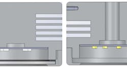
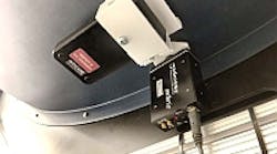
The model mrg-f-6 has a nominal payload of 6 kg, 6 axes, and a weight of 51 kg. Its work envelope volume is 2.84 m3; its maximum work envelope radius is 983 mm. The system's position repeatability of < ±0.02 mm and angle repeatability of < ±0.005° enables accurate measurements. Available detectors are frc'3 (radiometer/photometer), spec'3 (spectrometer), spr'3 (spectroradiometer), luca (luminance camera system, monochrome), and luca'color (luminance camera system, color version). Detectors can be mounted on wall, floor, ceiling, or the proprietary rail system. Measurement data is configuration-dependent and includes luminous intensity distribution (LID), luminous flux, colorimetric data, luminance, ray data, etc.
Depending on the configuration, several applications can be realized by one single device. Options are goniophotometer (far field), goniospectroradiometer (far field), luminance goniometer, luminance goniometer (color version), ray data goniometer (near field), ray data goniometer (near field, polychromatic), and goniometer system for measurement of retro-reflection. Additionally, a vertically movable installation of the Robogonio as well as of the detectors is possible by the proprietary rail system accessory.
